Underwater tunnel shield construction excavation face stability evaluation method, system and equipment
A technology for underwater tunnels and evaluation methods, which is applied in data processing applications, predictions, instruments, etc., and can solve problems such as damage to surrounding buildings, instability of excavation surfaces, and shield machine headings
Pending Publication Date: 2019-10-25
SHANDONG UNIV +1
3 Cites 4 Cited by
AI-Extracted Technical Summary
Problems solved by technology
Maintaining the stability of the excavation surface during shield excavation is the key to ensuring construction safety. Once the excavation surface is unstable, it will cause excessive deformation of the soil or even collapse, resulting in a series of serious consequences such as damage to surrounding buildings.
Large-diameter shield tunnels are faced with complex hydrogeology, and the excavation plan is difficult to implement, and it is prone to safety accidents such as the ins...
Abstract
The invention provides an underwater tunnel shield construction excavation face stability evaluation method, system and equipment, and the method comprises the steps: determining an excavation face stability evaluation index based on a shield construction excavation face instability mechanism; dividing the stability of the excavation surface into a plurality of grades, establishing each grade space, and determining the quantitative interval of each evaluation index in each grade; calculating a combined weight of each stability evaluation index by adopting a combined weighting method, and taking the combined weight as a judgment basis of the influence of the evaluation indexes on an evaluation result; and constructing an ideal point evaluation function by adopting an ideal point method so as to represent the membership degree of the to-be-evaluated object to each grade, calculating the grade membership degree of the to-be-evaluated section in each grade of the evaluation system, and determining the stability grade of the excavation surface in the construction process of the evaluation section.
Application Domain
ForecastingDesign optimisation/simulation +2
Technology Topic
InstabilityEvaluation function +4
Image
Examples
- Experimental program(1)
Example Embodiment
[0033] The disclosure will be further described below in conjunction with the drawings and embodiments.
[0034] It should be pointed out that the following detailed descriptions are all illustrative and are intended to provide further descriptions of the present disclosure. Unless otherwise indicated, all technical and scientific terms used herein have the same meaning as commonly understood by those of ordinary skill in the technical field to which the present disclosure belongs.
[0035] It should be noted that the terms used here are only for describing specific embodiments, and are not intended to limit the exemplary embodiments according to the present disclosure. As used herein, unless the context clearly indicates otherwise, the singular form is also intended to include the plural form. In addition, it should also be understood that when the terms "comprising" and/or "including" are used in this specification, they indicate There are features, steps, operations, devices, components, and/or combinations thereof.
[0036] Research on the instability records of the shield construction excavation face and the physical and mechanical characteristics of the Yangtze River Basin, analyze the factors affecting the stability of the shield construction excavation face, and finally determine through engineering experience and known domestic and foreign shield risk accidents Factors affecting the stability of the excavation face of shield tunneling, a system for evaluating the stability of the excavation face of shield tunneling is constructed, and the combined weighting method is used to obtain the weights of the factors affecting each index. The ideal point method is used, and then the ideal point method is used to construct the excavation surface stability evaluation model, and the stability of the excavation surface is evaluated by calculating the degree of membership of the stability of different construction sections.
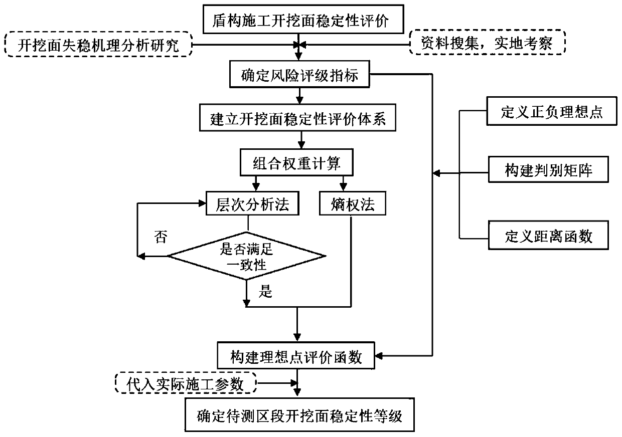
[0037] Specific, such as figure 1 As shown, including the following steps:
[0038] Step 1: Determine the stability evaluation index of the excavation surface by studying the mechanism of the instability of the excavation face of the shield construction, and referencing the existing literature.
[0039] Step 2: Divide the excavation surface stability into 5 levels, the level set C={Underwater tunnel shield construction excavation surface stability level}={C1, C2, C3, C4, C5} Establish and determine the level space Each evaluation index is quantified in each level.
[0040] Step 3: Use the combined weighting method to calculate the combined weight of each stability evaluation index as the basis for judging the influence of the evaluation index on the evaluation result.
[0041] Step 4: Use the ideal point method to construct the ideal evaluation function to express the degree of membership of the object to be evaluated to each level.
[0042] Step 5: Calculate the degree of membership of each level of the evaluation system for the section to be tested, and determine the stability level of the excavation surface during the construction of the evaluation section.
[0043] among them:
[0044] Determination of risk indicators in step one
[0045] Collect domestic and foreign mud-water shield construction cases and accident related data, combine mud-water balance shield related data and a large number of documents, and analyze the mechanism of shield construction excavation face instability, and determine the factors affecting the stability of shield construction excavation face. Determine the stability evaluation index of the excavation face.
[0046] Step 2: Classification of the stability grade of the excavation face
[0047] For the evaluation index of the stability of the excavation surface of the shield construction that has been determined in step 1, the stability evaluation system of the excavation surface is established in combination with the actual working conditions, and the stability of the excavation surface is graded, and according to the characteristics of each evaluation index and At the current stage of construction level, different methods are used to quantify the stability evaluation index. The stability of the excavation face is divided into five grades, and an evaluation system for the stability of the excavation face is established.
[0048] (1) Tunnel buried depth: As the buried depth of the tunnel increases, the overburden height of the tunnel construction excavation surface increases at the same time as the covering water, and the water and soil pressure increases, which increases the risk of the tunnel construction excavation surface. Use the buried depth H of the tunnel in actual working conditions, that is, the distance between the upper surface of the tunnel and the surrounding rock and the sea level (distance from the surface of the non-sea area) as the evaluation index. For subsea tunnels within 200m from the sea level, the Divided into five risk levels.
[0049] (2) Cover-span ratio: Cover-span ratio is the ratio of the thickness of the surrounding rock layer over the tunnel to the diameter of the tunnel. In a shield construction tunnel, the height of the cover of the tunnel construction excavation surface increases at the same time, the weight increases, the cover-span ratio increases, and the water The pressure has a greater impact on the stability of the tunnel and will reduce the stability of the excavation surface.
[0050] (3) Internal friction angle: The internal friction angle of the rock mass forming a stable mud film in front of the excavation is also an important evaluation index for the stability of the excavation surface. The greater the friction angle in the soil before the excavation, the stability of the excavation surface Higher.
[0051] (4) Cohesion of the soil layer: Cohesion is one of the important indexes of the shear strength of rock and soil, and it can also be used as an important evaluation index of the stability of the mud film of the excavation surface. The surrounding rock layers of the excavation surface are within a certain range , The relatively high cohesive force is easy to form a stable and good mud film on the excavation surface, while improving the strength of the excavation surface.
[0052] (5) Groundwater status: The influence of groundwater on the stability of the excavation surface during shield tunneling is mainly manifested by pore water pressure on the excavation surface. During the construction process, the pore water in front of the excavation will penetrate the excavation surface and cause the excavation surface. The groundwater is used as the evaluation factor for the stability of the excavation surface of the shield tunneling, and the natural water content of the formation is used as the evaluation index for the groundwater content.
[0053] (6) Soil permeability: According to the stability mechanism of the excavation surface of the slurry shield, the soil permeability of the excavation surface is small, and it is easy to form a weakly permeable mud film. The stability is easy to maintain. On the contrary, it is more difficult to form and affect Stability of the excavation surface. Since the permeability coefficients of the soil in the middle and lower reaches of the Yangtze River differ by orders of magnitude, the permeability parameters of the soil are used as the scoring standard for permeability and the permeability is used as the stability evaluation index. As shown in Table 1:
[0054] Table 1 Permeability of soil
[0055]
[0056]
[0057] (7) Construction and tunneling status
[0058] For mud-water balance shield construction, the tunneling speed under normal construction tunneling conditions is generally 20-50mm/min. It is known that the tunneling speed of the slurry shield is 92mm/min. The tunneling speed of the shield machine can represent the stable state of the excavation surface during the construction process. The tunneling speed of shield tunneling is relatively fast in low-risk sections, and the tunneling speed of shield tunneling in high-risk sections is relatively slow or even stagnant. The shield tunneling speed is given priority as a good evaluation index reflecting the reasonableness of construction parameters and at the same time as an evaluation index for evaluating the stability of the excavation surface. Taking into account the complex conditions of the actual construction and the limited parameters of the shield machine's machine performance, the quantified tunneling speed evaluation index is divided into five levels for the tunneling state of the shield construction. The establishment of the excavation face stability evaluation system is shown in Table 2:
[0059] Table 2 Tunneling status of shield construction
[0060]
[0061] Step two: Finally, establish an evaluation system for the stability of the excavation face during shield construction, as shown in Table 3:
[0062] Table 3 Stability rating evaluation system
[0063]
[0064]
[0065] Step 2: The stability of the excavation surface is divided into 5 grades. The grade set C={Stability grade of the excavation surface of the Jianghai tunnel shield construction}={C1, C2, C3, C4, C5} Establish the grade space and determine each The evaluation index is quantified in each level. It also stipulates that C1={excavation surface is stable, no risk}; C2={excavation surface is relatively stable, risk is negligible}; C3={something less stable, there is risk}; C4={poor stability}; C5= {Poor stability}; The stability description for the corresponding level is as above.
[0066] Calculation of evaluation index weight in step three
[0067] In step three, the analytic hierarchy process is used to calculate the subjective weight of the evaluation index, the entropy method is used to calculate the objective weight of the evaluation index, and the final combined weight of the evaluation index is calculated according to the degree of difference between the two weights. The specific calculation process is as follows:
[0068] (1) Subjective weight calculation
[0069] In step three, the analytic hierarchy process is used to compare evaluation indicators in pairs. The decision-maker draws on the recommendations of experts and scholars and uses a scale of 1-9 as the index importance evaluation standard to rank the overall importance of the indicators and construct a judgment matrix. G n×n (Where a ij Represents the j-th value of the i-th group of impact indicators):
[0070]
[0071] Judgement matrix construction form
[0072] The degree of influence of the evaluation index on the decision-making result takes the scale of 1-9 as the quantitative expression of the index's importance. Such as a ij Indicates that the relative importance of index i and index j is a ij , The same index i is compared with index j, and the degree of importance is 1/a ij. Using the maximum eigenvalue method to judge matrix G n×n. Find the maximum eigenvalue λ max And the corresponding feature vectors are calculated by formulas (1) to (4) to obtain the importance ranking of the evaluation indicators.
[0073] Finally, in order to avoid ranking contradictions in the importance comparison process due to too many indicators in the decision-making process, the consistency ratio index CR is introduced, and CR=CI/RI is defined, where the consistency index CI and the average consistency index RI calculation formulas are as formulas (3) ~ (5). And think that when CR <0.1, the judgment matrix G has acceptable consistency, and the weight value w calculated by the analytic hierarchy process is obtained at this time i (w 1 ,w 2 ,w 3...w n ). On the contrary, it is considered that the degree of deviation of the judgment matrix G from the consistency is too large, and the element value in G needs to be modified.
[0074]
[0075]
[0076]
[0077] CR={(λ max -n)(n-1)}/RI (4)
[0078] (2) Objective weight calculation
[0079] In step three, the entropy weight method is used to calculate the objective weight of the evaluation index. The entropy weight method has the characteristic of objectively relying on objective data. By defining the data information reflected by the sample data as entropy, the evaluation index weight is determined based on the sample entropy value and the dispersion degree of the index numerical variation data, and the entropy weight method is used to determine the index weight divided into The following steps:
[0080] 1) Data normalization
[0081] In order to avoid the influence of the indicator unit on the calculation result, the value of each indicator is normalized, and the data sample matrix M(x ij ) m×n , For the positive index, that is, the larger the index, the more stable the excavation surface, the optimal solution is selected as For negative indexes, that is, the larger the index, the more unstable the excavation surface is, the optimal solution is selected Perform normalization according to formula (6):
[0082]
[0083] Obtain the normalized matrix R=(r ij ) m×n
[0084] 2) Define the entropy
[0085] Assuming that there are m indicators and n objects to be evaluated in a decision-making process, the entropy H of the i-th indicator is defined according to the entropy weight method i for:
[0086]
[0087] Where When f ij = 0, let f ij lnf ij =0.
[0088] 3) Define entropy weight
[0089] Obtain the evaluation index entropy H i Then, define the entropy weight of the indicator, which is the objective weight of the indicator e i :
[0090]
[0091] Where 0≤e i ≤1,
[0092] Finally obtain the objective weight e of the evaluation index calculated by the entropy method i (e 1 ,e 2 ,e 3...e m ).
[0093] (3) Weight combination
[0094] In step 3, in order to ensure that the degree of difference between the weight values obtained by the two methods is consistent with the degree of difference of the corresponding distribution coefficient, the distance function f(x) is introduced to express the degree of difference in the weight of each index, using formula (8)~ (9) Calculate the distribution coefficients α and β of the two weights.
[0095]
[0096] Let the combination weight be W i , The combined weight value is the linear weighting of both:
[0097] W i =αw i +βe i (9)
[0098] In order to make the degree of difference between subjective and objective weights consistent with the degree of distribution coefficient difference, the distance function should satisfy:
[0099] f(w i ,e i )=(α-β) 2 (10)
[0100] In the formula, α and β are the distribution coefficients of the two weights. In order to make the degree of difference between the different weights and the degree of difference between the distribution coefficients the same, the two formulas are equal and the constraints are imposed:
[0101] α+β=1 (11)
[0102] In summary, the simultaneous equations, let:
[0103]
[0104] The weights obtained by the two calculation methods are obtained through simultaneous equations (8) to (11). Substituting the obtained distribution coefficient into formula (8), the final weight W can be obtained i.
[0105] Step four: construct ideal point method evaluation function
[0106] In step 4, the risk assessment indicators of the shield construction tunnel excavation surface are divided into two types: positive indicators and inverse indicators. The positive indicators increase with the increase of the index value, and the greater the collapse risk level is, the opposite is the case for the inverse indicators. Assuming that the risk evaluation index of the shield construction tunnel excavation surface shows a monotonous change trend, determine the positive ideal point and the negative ideal point of each risk evaluation index;
[0107] When the risk assessment index of the shield construction excavation face is a positive index, the positive ideal point and the negative ideal point are:
[0108]
[0109] When the risk assessment index of the shield construction excavation face is the inverse index, the positive ideal point and the negative ideal point are:
[0110]
[0111] Where r i Is the i-th evaluation index value, f i (a), f i (b) are the positive ideal point and the anti-ideal point corresponding to the i-th evaluation index.
[0112] The ideal evaluation function in step 4 is the distance from the indicator to the positive ideal point and the anti-ideal point. The closer the solution of the index is to the positive ideal point and the further away from the anti-ideal point, the better the solution. The definition in n-dimensional space is:
[0113] ||f(x)-f * (+)||→min, ||f(x)-f * (-)||→max
[0114] Construct an ideal evaluation function to define the distance between a positive ideal point and an anti-ideal point of the judgment evaluation index. The ideal evaluation function most often uses the Minkowski distance, and the Euclidean distance is generally used to define the evaluation index to The distance between the positive ideal point and the anti-ideal point. (The following is the definition method using Euclidean distance, the specific method depends on the specific situation):
[0115] The distance between the i-th risk index value and its positive ideal point can be expressed as:
[0116]
[0117] The distance between the i-th risk index value and its anti-ideal point is expressed as:
[0118]
[0119] Where x imax And x imin Is the upper and lower limits of the range of each indicator.
[0120] Step 5: Calculate the closeness to the ideal point and evaluate the risk level of the evaluation object.
[0121] The calculation formula for the closeness of the evaluation index to the corresponding ideal point is T=D2/(D1+D2)
[0122] Where D 1 D 2 They are the distance between the evaluation index and the positive ideal point and the anti-ideal point.
[0123] Through the calculation of the closeness of the ideal point, the risk level of the evaluation object is evaluated, and the risk assessment level is the level with the higher calculation closeness. Calculate the degree of membership of the measured section to determine the stability level of the excavation face during the construction process of the evaluation section.
[0124] Those skilled in the art should understand that the embodiments of the present disclosure can be provided as methods, systems, or computer program products. Therefore, the present disclosure may adopt the form of a complete hardware embodiment, a complete software embodiment, or an embodiment combining software and hardware. Moreover, the present disclosure may adopt the form of a computer program product implemented on one or more computer-usable storage media (including but not limited to disk storage, CD-ROM, optical storage, etc.) containing computer-usable program codes.
[0125] The present disclosure is described with reference to flowcharts and/or block diagrams of methods, devices (systems), and computer program products according to embodiments of the present disclosure. It should be understood that each process and/or block in the flowchart and/or block diagram, and the combination of processes and/or blocks in the flowchart and/or block diagram can be implemented by computer program instructions. These computer program instructions can be provided to the processor of a general-purpose computer, a special-purpose computer, an embedded processor, or other programmable data processing equipment to generate a machine, so that the instructions executed by the processor of the computer or other programmable data processing equipment are generated for use In the process Figure one Process or multiple processes and/or boxes Figure one A device with functions specified in a block or multiple blocks.
[0126] These computer program instructions can also be stored in a computer-readable memory that can guide a computer or other programmable data processing equipment to work in a specific manner, so that the instructions stored in the computer-readable memory produce an article of manufacture including the instruction device. The device is implemented in the process Figure one Process or multiple processes and/or boxes Figure one Functions specified in a box or multiple boxes.
[0127] These computer program instructions can also be loaded on a computer or other programmable data processing equipment, so that a series of operation steps are executed on the computer or other programmable equipment to produce computer-implemented processing, so as to execute on the computer or other programmable equipment. Instructions are provided to implement the process Figure one Process or multiple processes and/or boxes Figure one Steps of functions specified in a box or multiple boxes.
[0128] The foregoing descriptions are only preferred embodiments of the present disclosure and are not used to limit the present disclosure. For those skilled in the art, the present disclosure may have various modifications and changes. Any modification, equivalent replacement, improvement, etc., made within the spirit and principle of the present disclosure should be included in the protection scope of the present disclosure.
[0129] Although the specific embodiments of the present disclosure are described above in conjunction with the accompanying drawings, they do not limit the scope of protection of the present disclosure. Those skilled in the art should understand that on the basis of the technical solutions of the present disclosure, those skilled in the art do not need to make creative efforts. Various modifications or variations that can be made are still within the protection scope of the present disclosure.
PUM


Description & Claims & Application Information
We can also present the details of the Description, Claims and Application information to help users get a comprehensive understanding of the technical details of the patent, such as background art, summary of invention, brief description of drawings, description of embodiments, and other original content. On the other hand, users can also determine the specific scope of protection of the technology through the list of claims; as well as understand the changes in the life cycle of the technology with the presentation of the patent timeline. Login to view more.