[0022] In order to make the objectives, features, and advantages of the present invention more obvious and understandable, the technical solutions in the embodiments of the present invention will be described clearly and completely with reference to the accompanying drawings in the embodiments of the present invention. Obviously, the described The embodiments are only a part of the embodiments of the present invention, but not all the embodiments. Based on the embodiments of the present invention, all other embodiments obtained by those skilled in the art without creative work shall fall within the protection scope of the present invention.
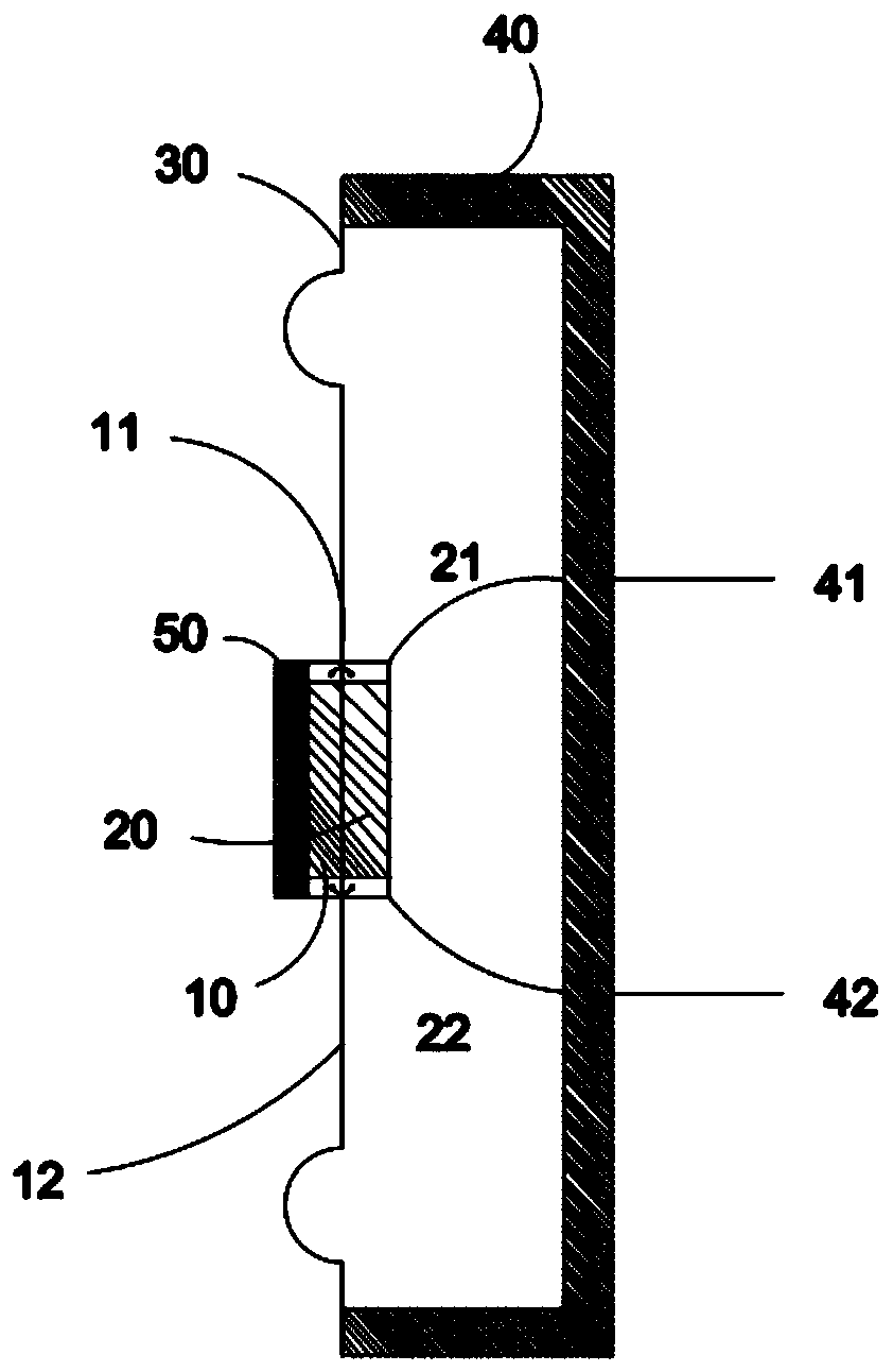
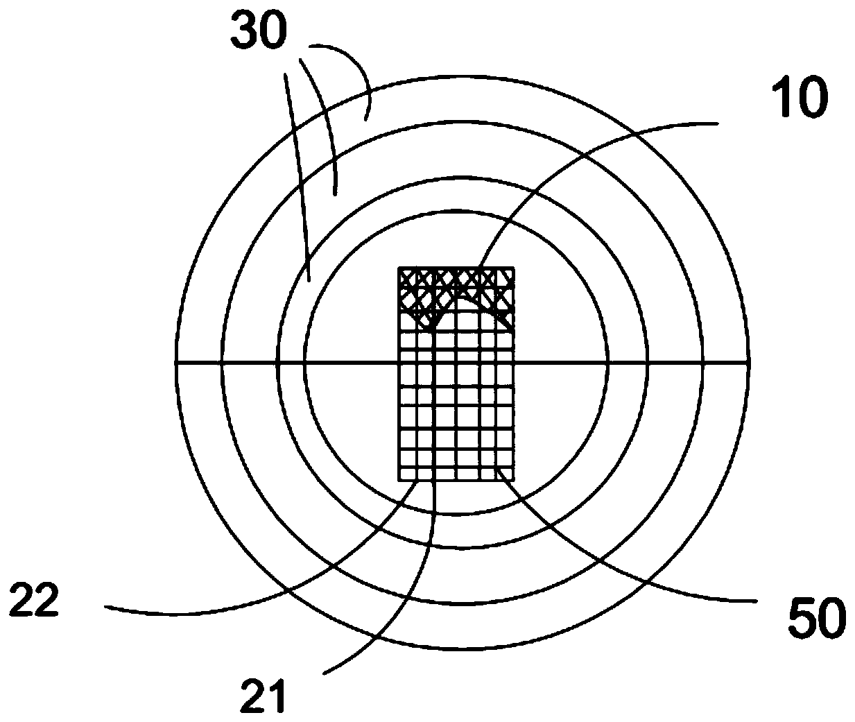
[0023] This embodiment provides a new type of piezoelectric speaker. For specific structure, see figure 1 with figure 2 , figure 1 Is a cross-sectional view of a new piezoelectric speaker provided by an embodiment of the present invention; figure 2 It is a top view of a new piezoelectric speaker provided by an embodiment of the present invention.
[0024] The new piezoelectric speaker includes: a first piezoelectric sheet 10, a second piezoelectric sheet 20, a bass diaphragm 30 and a sound cavity 40;
[0025] The first piezoelectric sheet 10 and the second piezoelectric sheet 20 are respectively pasted on both sides of the bass diaphragm 30 to form a piezoelectric sheet bass diaphragm structure.
[0026] The first pressing piece 10 and the second pressing piece 20 are connected in parallel;
[0027] Specifically, the first pressing piece 10 and the second pressing piece 20 are both rectangular piezoelectric ceramic pieces, and both ends of the first pressing piece 10 are connected to the second pressing piece through the first parallel lead 11 and the second parallel lead 12 respectively. The two ends of the sheet 20 are connected.
[0028] The piezoelectric sheet bass diaphragm structure is pasted and installed at the opening of the acoustic cavity 40.
[0029] Further, the two ends of the second piezoelectric sheet 20 respectively lead out the first lead 21 and the second lead 22; the acoustic cavity has a first lead 41 and a second lead 42, wherein the first lead 41 and the first lead 21 The second lead pin 42 is connected to the second lead 22.
[0030] In this embodiment, the first piezoelectric sheet and the second piezoelectric sheet are respectively pasted on both sides of the bass diaphragm. The bass diaphragm can produce bass. Two piezoelectric sheets are pasted on both sides of the bass diaphragm to form a push-pull Type piezoelectric drive, that is, when the first piezoelectric sheet and the second piezoelectric sheet add electrical signals, the vibration force generated on the bass diaphragm forms a push-pull in the same direction, which makes the bass diaphragm twice The maximum amplitude value of the speaker can increase the sound pressure output by the speaker. The new piezoelectric speaker in this embodiment can emit bass and the sound is loud enough, so that the piezoelectric speaker can be used as widely as the dynamic speaker, which improves the performance of the piezoelectric speaker. Scope of application.
[0031] Further, the bass diaphragm 30 is a circular diaphragm with a rubber edge with a hardness of 55 degrees, and the rubber edge has 1 to 3 protrusions to form a rubber wave edge. among them, figure 1 Two protrusions are shown in, which are respectively close to the two ends of the bass diaphragm 30, that is, the two protrusions are closer to the two ends of the bass diaphragm 30 relative to the center of the bass diaphragm 30.
[0032] In addition, the bass diaphragm 30 is made of paper fiber mixed with wool fiber material. This combination of shape and material has better low-frequency vibration characteristics and can emit lower frequency sounds.
[0033] Furthermore, the new piezoelectric speaker further includes a sound vibration plate 50, which is pasted on the bass diaphragm 30. The sound vibration plate 50 is specifically a honeycomb resonance plate, which includes a plurality of honeycombs, and each honeycomb forms a bass resonance cavity. The multiple bass resonant cavities in the honeycomb vibrating plate can significantly improve the bass of the new piezoelectric speaker, from the original minimum 400Hz (Hertz) to 250Hz.
[0034] The honeycomb resonance plate is pasted on the bass diaphragm 30. When the first piezoelectric sheet 10 and the second piezoelectric sheet 20 obtain electrical signals to generate electrical vibration, the bass diaphragm 30 vibrates, and at the same time drives the honeycomb resonance plate to generate resonance vibration. Simultaneously emit the same sound wave, after adding the honeycomb resonance board, the volume can be increased by 3dB, and the effect of increasing the volume is obvious.
[0035] Further, to increase the driving voltage of the piezoelectric sheet, the piezoelectric sheet is a voltage-driven element, and the output of the usual power amplifier circuit, especially the low-power power amplifier circuit, is only about 1-3v, which cannot effectively drive the piezoelectric sheet to reach the maximum amplitude. Therefore, in this embodiment, by increasing the boost inductance, the signal voltage applied to both ends of the piezoelectric sheet is increased by 7 volts, thereby driving the piezoelectric sheet to the maximum amplitude, so that the output sound of the new piezoelectric speaker can be maximized.
[0036] Specifically, see image 3 , image 3 In this embodiment, the boost circuit diagram of the new piezoelectric speaker is set at the input end of the new piezoelectric speaker. A boost inductor 60 is set at the input end of the new piezoelectric speaker. The output end of the boost inductor 60 is connected in parallel with the first piezoelectric sheet 10 and the second piezoelectric sheet. The sheet 20 is connected, and the input end of the boost inductor 60 is electrically connected to the output end of the amplifier (not shown in the figure) of the new piezoelectric speaker.
[0037] Specifically, the boost inductor 60 is an eight-fold boost inductor.
[0038] The working principle of the above circuit is: the signal output by the amplifier is sent from the input terminal to the primary winding of the boost inductor 60, and the signal is increased by 7 times through the boost winding of the boost inductor 60, that is, the input weak signal is increased to more than 7v , And then applied to the two first piezoelectric slices and second piezoelectric slices connected in parallel, so that the voltage requirement of the maximum vibration amplitude can be achieved, and a greater sound can be obtained.
[0039] The sounding principle of the above-mentioned speaker is: the electric signal of the sound passes through the above-mentioned booster circuit, and is outputted to the first piezoelectric sheet and the second piezoelectric sheet after the inductive sound pressure is boosted. The first piezoelectric sheet and the second piezoelectric sheet obtain The high-voltage electrical signal generates electric vibration and the bass diaphragm vibrates. At the same time, the honeycomb resonance plate pasted with the bass diaphragm generates resonant vibration, and simultaneously emits sound waves of the same frequency.
[0040] The new piezoelectric speaker provided in this embodiment has extremely low power consumption. Compared with a dynamic speaker with the same sound power, its power consumption is only 1/20, which greatly reduces power consumption, saves power, and makes the whole machine stand-by time Long enough; extremely light weight: Compared with a dynamic speaker that emits the same sound pressure level, its weight is only 1/4 of a dynamic speaker; versatile: it can be widely used in audio and various sound equipment, low power consumption , Light weight, especially suitable for current portable sound-producing equipment, can greatly extend the battery life and life. Since the piezoelectric speaker is not a power component, the power amplifier configured for this does not need to add a heat sink. Reduce material consumption and reduce material costs.
[0041] The above is a description of the new piezoelectric speaker provided by the present invention. For those skilled in the art, according to the ideas of the embodiments of the present invention, there will be changes in the specific implementation and the scope of application. In summary, the content of this specification It should not be understood as a limitation to the present invention.