
Pressurised fluid flow system for a dth hammer and reverse circulation hammer based on same

A technology of pressurized fluid and flow system, which is applied in the direction of drilling drives, drill bits, earthwork drilling and production in the wellbore, which can solve the problems of negative impact of drill bit design, insufficient drag surface of keyway, increase of manufacturing cost, etc., and achieve deterioration cycle Efficiency, improved reliability, effect of increased passive volume

Active Publication Date: 2019-10-25
海梅安德烈斯阿罗斯
View PDF22 Cites 0 Cited by
  • Summary
  • Abstract
  • Description
  • Claims
  • Application Information

AI Technical Summary

Problems solved by technology

[0067] The disadvantages of this flow system are the same as those associated with Type A and Type D flow systems, in particular negatively impacting the design of the bit in two respects
The first aspect is that multiple manufacturing processes are required to create channels in the outer surface of the bit, which increases the manufacturing cost of the hammer
A second aspect is that, due to the presence of these channels, the drag surface of the keyways (which depends on the contact area of ​​each keyway individually and the total number of keyways) may not be sufficient in some applications
[0074] The disadvantages in this example (patent US4819746) are the same as those of the Type A flow system, and the design of the bit is also negatively affected in the same two aspects already mentioned for the Type 1 flow system plus a third

Method used


Image

  • Pressurised fluid flow system for a dth hammer and reverse circulation hammer based on same
  • Pressurised fluid flow system for a dth hammer and reverse circulation hammer based on same
  • Pressurised fluid flow system for a dth hammer and reverse circulation hammer based on same

Examples


Embodiment Construction

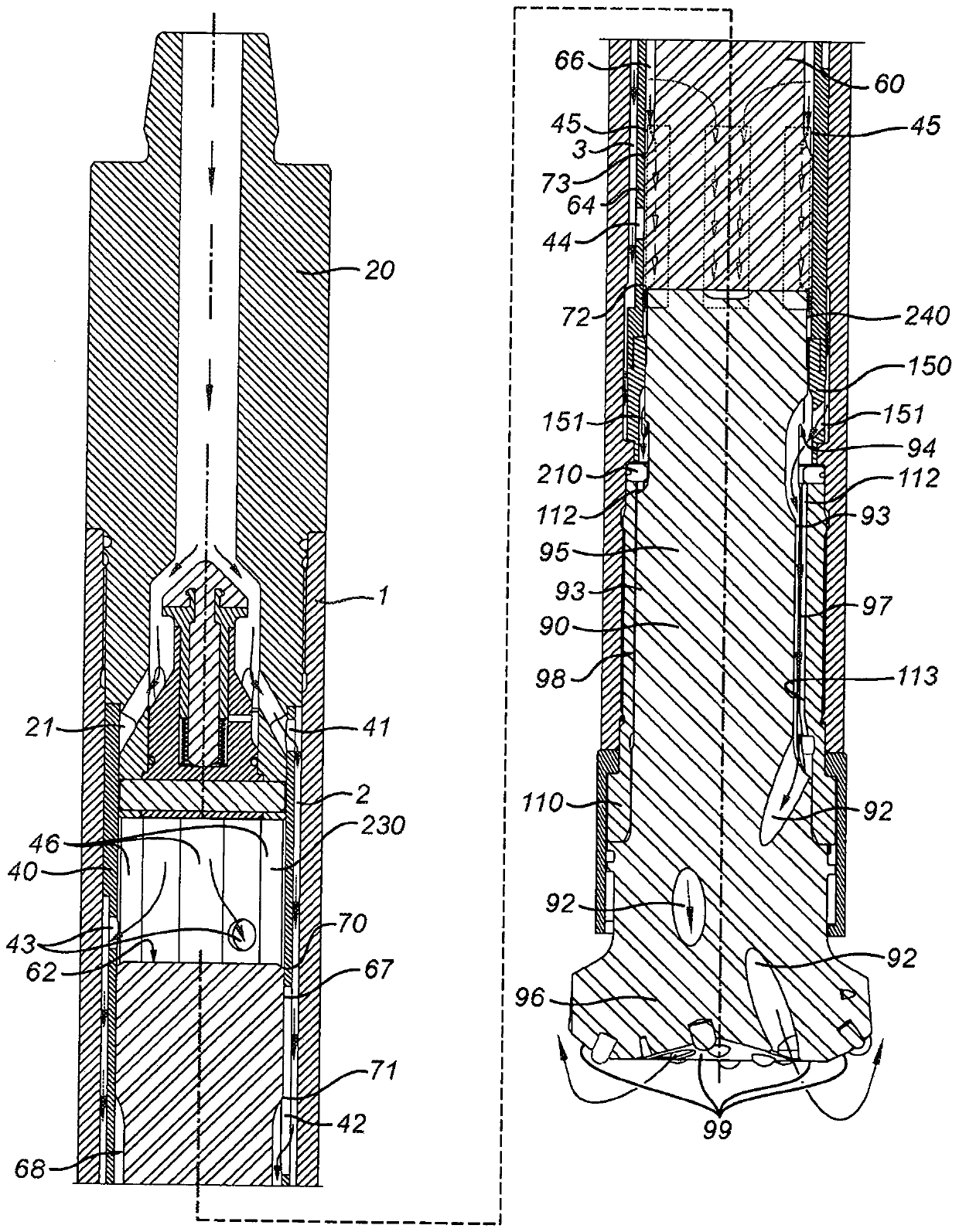
[0103] refer to Figure 1 to Figure 7 , showing a positive cycle DTH hammer, which includes the following main components:

[0104] a cylindrical housing (1) with a rear end and a front end;

[0105] a drive connector (110) mounted to the front end of said housing (1) and having an inner surface (113) with a keyway (112) machined thereon;

[0106] a rear connector (20) secured to the rear end of said housing (1) for connecting the hammer to a source of pressurized fluid;

[0107] a piston (60), which is slidably and coaxially arranged inside said casing (1), and said piston has a front chamber (240) and a rear chamber at opposite sides of said piston (60) (230) capable of reciprocating movement by pressure variation of pressurized fluid contained therein, said piston (60) having a plurality of outer sliding surfaces (64, 67); and

[0108]a drill bit (90) slidably mounted on said driver sub (110), the sliding movement of said drill bit (90) being limited by a bit holder (210...


PUM


Abstract

The invention relates to a pressurized fluid flow system for a reverse circulation down-the-hole hammer which comprises a coaxial jacket arranged between an outer casing and a piston which reciprocates due to changes in the pressure of the pressurized fluid contained inside a front chamber and a rear chamber located at opposite ends of the piston, the feeding / discharge of fluid to / from these chambers takes place through sets of feeding and discharge channels defined by recesses in the outer surface of the jacket and arranged in parallel, the flow of the fluid towards the inside and from the front and rear chambers being controlled exclusively by the overlap of the piston and the jacket, and by channeling the flow of fluid under the inner surface of the jacket and over the outer surface ofthe piston. A hammer provided with such a system has a drill bit with one or more flushing passages.

Description

technical field [0001] The present invention generally relates to a pressurized fluid flow system for impact mechanisms operated using pressurized fluid, particularly for DTH (Down-The-Hole: down-the-hole) hammers, and more particularly for positive cycle DTH hammers, And the invention relates to a DTH hammer with said system. Background technique [0002] DTH Hammer [0003] There are various percussion drilling mechanisms that use pressurized fluid as the device for transmitting power. These percussion drilling mechanisms include DTH hammers which are widely used in the drilling industry, mining industry and civil engineering and construction of water, oil and geothermal wells. A cylindrical DTH hammer is used by assembling it on a drilling rig at the surface of the earth. The drilling rig also includes a drill string comprising rods assembled together, understood as the rear end further distal from the hammer bit (elements described in the specification below) assemble...

Claims


Application Information

Patent Timeline
IPC IPC(8): E21B4/14E21B10/36E21B10/38
CPCE21B4/14E21B10/36E21B10/38
Inventor 海梅·安德烈斯·阿罗斯
Owner 海梅安德烈斯阿罗斯
Learn More