Antifatigue torsion beam for plate formation

A technology of anti-fatigue and sheet metal, which is applied in the field of auto parts, can solve the problems of affecting welding efficiency and quality, reducing the thickness of welding joints, and reducing the strength of welding joints, etc., and achieves the effects of increasing fatigue resistance, improving toughness and improving precision

Pending Publication Date: 2019-10-29
天人汽车底盘(芜湖)股份有限公司
View PDF0 Cites 2 Cited by
  • Summary
  • Abstract
  • Description
  • Claims
  • Application Information

AI Technical Summary

Problems solved by technology

The welding step of sheet metal forming refers to welding the gap between the two bending parts through welding equipment, so that the beam is finally in a closed state, but before welding, the beam is bent by the sheet metal, and the beam has recovery deformation In this way, during the welding process, the two bending parts are easy to move away from each other, which affects the efficiency and quality of welding
If the two bending parts are far away from each other during the welding process, the welded par

Method used


Image

  • Antifatigue torsion beam for plate formation
  • Antifatigue torsion beam for plate formation
  • Antifatigue torsion beam for plate formation

Examples


Embodiment 1

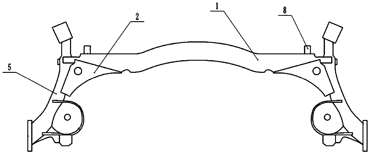
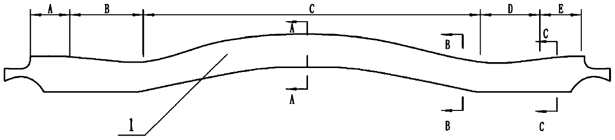
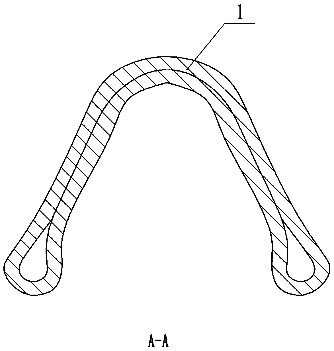
[0042] This embodiment relates to an anti-fatigue torsion beam formed from a sheet material, which is applied to an automobile torsion beam. combine figure 1 As shown, the automobile torsion beam includes a beam body 1 and a trailing arm 5, and the trailing arm 5 is welded to both ends of the beam body 1. Specifically, the two ends of the beam body 1 are provided with interfaces, combined with figure 2 As shown, the edges of the joints at both ends of the beam body 1 are recessed towards the middle of the beam body 1, so that the joints at both ends of the beam body 1 can wrap the outer wall of the longitudinal arm 5 because the shape of the joint is arc-shaped, so that the longitudinal arm 5 is welded on the The beam body 1 is relatively smooth and smooth, and the welding strength between the longitudinal arm 5 and the beam body 1 can also be improved.

[0043] The two ends of the beam body 1 are provided with connecting parts for welding the reinforcing plate 2, and the re...

Embodiment 2

[0062] combine Image 6 As shown, the beam body 1 is fixed with an illumination mechanism 9 . Specifically, combine Figure 18 As shown, the lighting mechanism 9 includes a base plate 10 welded on the beam body 1, a lighting lamp 14 located on the base plate 10, and a protective cover 11 for covering the lighting lamp 14. The protective cover 11 can be locked by a block and a slot. Covered on the base plate 10 in a connected manner. combine Figure 19 As shown, the central position of the bottom of the base plate 10 is provided with a hinged hole 19, and the surrounding of the hinged hole 19 is provided with annularly distributed support holes 18. The number of rings of the support holes 18 in this embodiment is two rings, and the support holes of the inner ring The number of 18 is six, the number of supporting holes 18 of the outer ring is ten, and the insides of the supporting holes 18 are all bonded with magnets. combine Figure 18 As shown, the protective cover 11 is ...


PUM


Abstract

The invention relates to the field of automobile parts, in particular to an antifatigue torsion beam for plate formation. The beam comprises a beam body which is processed through a plate, and a firstclamping unit and a second clamping unit are arranged at the two ends of the plate respectively and integrally clamped in the formation step; the beam body is divided to two flaring segments, two transition segments and one middle segment, the middle segment is bent and is in an arch shape, the two transition segments are located at the two ends of the middle segment respectively, the two flaringsegments are located at the two ends of the transition segments respectively, the cross sections of the transition segments and the middle segment are in a V shape, and the depths of the V-shaped cross section shapes, from the middle of the middle segment to the transition segments, of the beam body are gradually reduced. The antifatigue capacity of the beam is improved.

Description

technical field [0001] The invention relates to the field of auto parts, in particular to an anti-fatigue torsion beam formed from sheet metal. Background technique [0002] The torsion beam is an important part of the automobile. During the operation of the automobile, it plays an important role in the shock absorption of the automobile, the transmission of loads, the reduction of the shaking of the vehicle, the provision of suitable freedom of movement for the wheels, and the assurance of the stability of the car body. to an important role. [0003] The torsion beam usually includes a crossbeam and a longitudinal arm. The longitudinal arm is welded at both ends of the crossbeam. During the operation of the car, the welding position of the longitudinal arm and the crossbeam is prone to breakage because the load of the car will change irregularly and irregularly. , so the life of the torsion beam is shorter, and the subsequent maintenance cost is relatively high. [0004] ...

Claims


Application Information

Patent Timeline
IPC IPC(8): B60G21/05B60Q1/00
CPCB60G21/051B60G2206/20B60Q1/00
Inventor 龚量亮
Owner 天人汽车底盘(芜湖)股份有限公司
Why Eureka
Try Eureka