

Wheel structure and canoeing using wheel structure
A wheel structure and kayak technology, applied in the field of ships, can solve problems such as laborious, expensive, and cost-increasing problems, and achieve the effect of easy operation and replaceable
- Summary
- Abstract
- Description
- Claims
- Application Information
AI Technical Summary
Problems solved by technology
Method used
Image

Examples
Embodiment 1
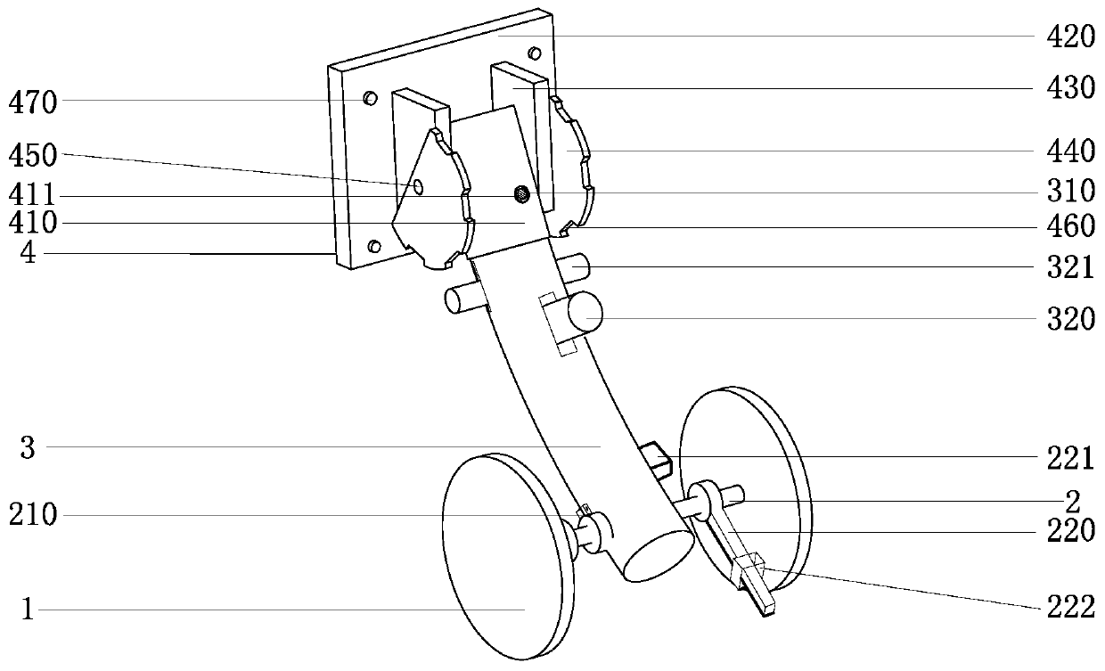
[0033] Such as figure 1 A wheel structure is shown, the main body of which is composed of a wheel body 1, a shaft 2 and a support rod 3, a two-way ratchet mechanism 210 is arranged at the connection position between the shaft 2 and the support rod 3, and the ratchet wheel of the two-way ratchet mechanism 210 It is fixed on the shaft 2, and the pawl and the adjustment switch for controlling the pawl are set on the support rod 3. Under the action of the two-way ratchet mechanism 210, the shaft 2 can only be adjusted to rotate in one direction, and then it is set on both sides of the shaft 2. The wheel body 1 at the end will only be able to rotate in one direction along with the shaft 2 which can be adjusted.
[0034] In this embodiment, the shaft 2 is provided with a stop rod 220, and the stop rod 220 is loosely set on the shaft 2, that is, it is sleeved on the shaft 2 through a ring at one end, and stops when the shaft 2 rotates. The retracting rod 220 will not swing thereupon...
Embodiment 2
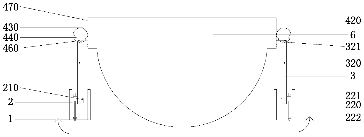
[0045] The difference of this embodiment on the basis of embodiment 1 is that in this embodiment, as image 3 As shown, the wheel structure is arranged on both sides of the hull of the kayak 6 through the connecting piece 4. This connection method is more suitable for the situation that the stern part does not have enough space to connect with the base 420, but there are enough places on both sides of the hull to connect with the base. The kayak 6 connected by 420; the connection method is specifically: the connecting piece 4 is arranged on both sides of the hull of the kayak 6 through the base 420, and the base 420 and the hull are installed through sealing screws 470; the support rod 3 of the wheel structure It is inserted into one end of the sleeve 410 of the connecting piece 4, and is flexibly connected with the connecting piece 4 through the limitation of the spring pin 310 and the positioning hole 411, so that the wheel structure is installed on both sides of the kayak 6 ...
Embodiment 3
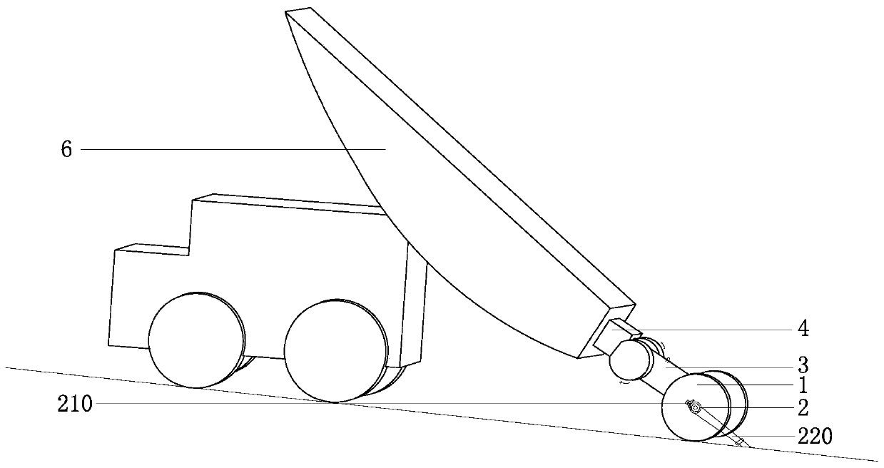
[0048] The difference of this embodiment on the basis of Embodiment 1 is that in this embodiment, the wheel structure is arranged on the bottom of the kayak 6 through the connecting piece 4, such as Figure 5 shown.
PUM
 Abstract
Description
Claims
Application Information