
Construction method for installing rubber waterstop on automatic folding type joint box of underground continuous wall

A technology for underground diaphragm walls and rubber waterstops, applied in water conservancy projects, artificial islands, sheet pile walls, etc., can solve problems such as easy damage to rubber waterstops and joint boxes, and difficulty in demoulding, so as to facilitate recycling , Improve the performance of water-proof and anti-seepage, and avoid damage

Active Publication Date: 2019-10-29
杭州悦为科技有限公司
View PDF5 Cites 2 Cited by
  • Summary
  • Abstract
  • Description
  • Claims
  • Application Information

AI Technical Summary

Problems solved by technology

[0002] The underground diaphragm wall often has water leakage as the enclosure structure of the foundation pit. There is a joint box (GXJ for short) installed with a rubber waterstop on the underground diaphragm wall, which has a good sealing effect on the water leakage at the joint of the underground diaphragm wall , but in the process of demoulding, it is difficult to demould the joint box and the cast-in-situ concrete underground diaphragm wall, and it is easy to damage the rubber waterstop and the joint box.

Method used


Image

  • Construction method for installing rubber waterstop on automatic folding type joint box of underground continuous wall
  • Construction method for installing rubber waterstop on automatic folding type joint box of underground continuous wall
  • Construction method for installing rubber waterstop on automatic folding type joint box of underground continuous wall

Examples


Embodiment Construction

[0044] In order to deepen understanding of the present invention, reference will be made below to the attached figure 1 to attach Figure 12 , the embodiments of the present invention are described in detail, the following embodiments are implemented on the premise of the technical solution of the present invention, and detailed implementation is provided, but the protection scope of the present invention is not limited to the following embodiments.

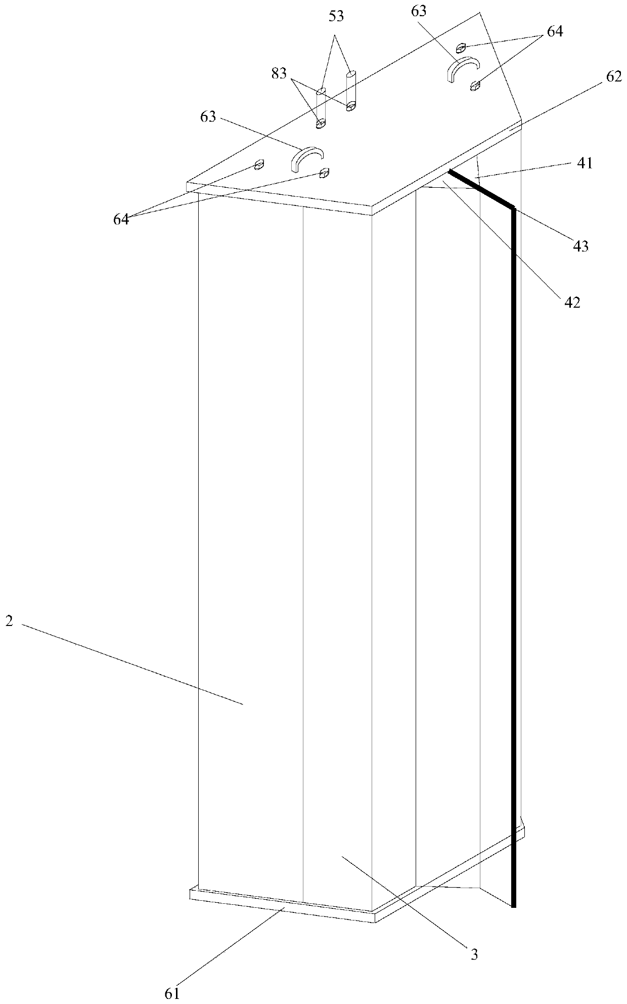
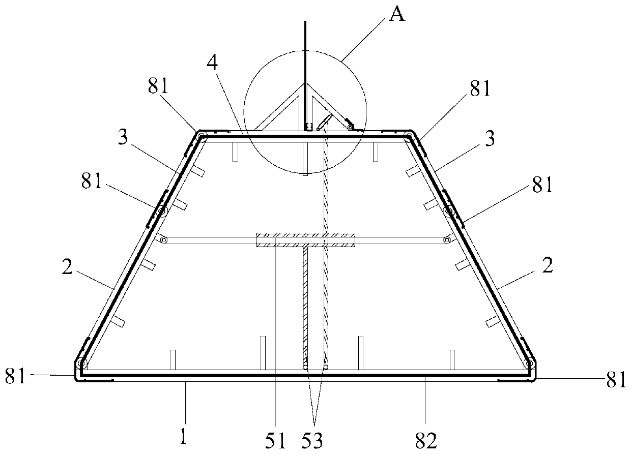
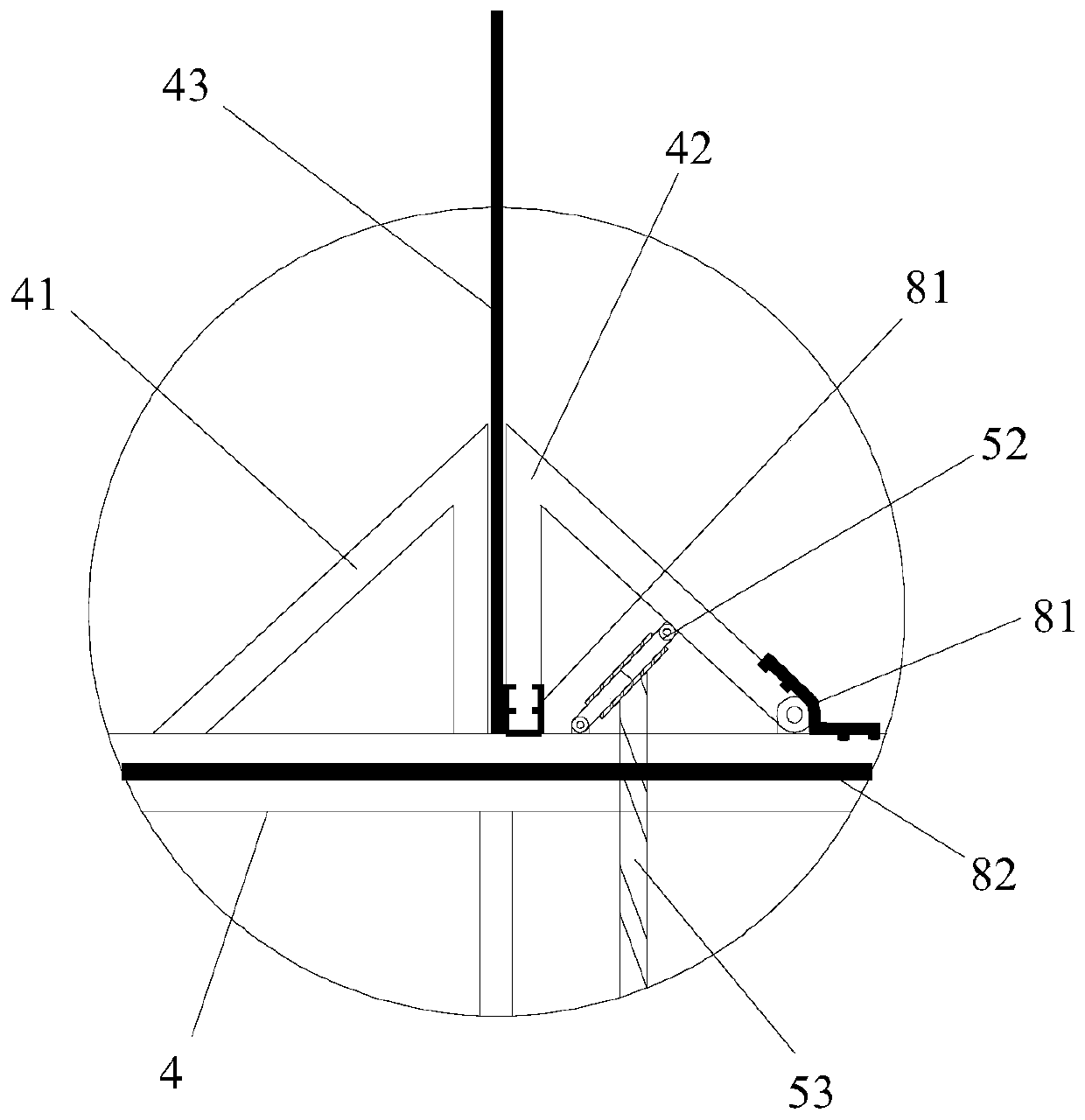
[0045] combined with figure 1 And attached figure 2 As shown, the present invention relates to an automatic folding joint box for a cast-in-situ concrete underground continuous wall, comprising a back panel 1, a rear side panel 2, a front side panel 3, a front panel 4, a folding hydraulic arm 51, a clamping hydraulic arm 52, Lower end plate 61, upper end plate 62 etc. are formed.

[0046] combined with figure 2 , attached Figure 4 ~ attached Figure 6 As shown, the back plate 1, the rear side plate 2, the front side plat...


PUM


Abstract

The invention relates to a construction method for installing a rubber waterstop on an automatic folding type joint box of an underground continuous wall. The method comprises the steps of guide wallconstruction, trench excavation, reinforcement cage binding and lowering, joint box assembling and installation, concrete pouring, joint box contraction and lifting out and the like. A back plate, rear side plates, front side plates and a front plate of the joint box are hinged to each other and are sealed by strip-shaped waterstop, a plurality of folding hydraulic arms are arranged between the rear side plates, a plurality of rubber waterstop clamping devices and clamping hydraulic arms are arranged on the front plate, the folding hydraulic arms and the clamping hydraulic arms are connected with a hydraulic pump through independent hydraulic pipes, and the joint box is connected into a whole through fastening pull rods; after the concrete of the underground continuous wall reaches a certain strength, the folding hydraulic arms are contracted, and the clamping hydraulic arm are stretched synchronously, so that the joint box integrally contracts and folds, the clamping device releases the rubber waterstop, and the joint box is lifted out. The water stop and seepage prevention performance of the joint of the concrete underground continuous wall can be improved, construction is convenient and fast, and economic and social benefits are good.

Description

technical field [0001] The invention relates to a construction method for an underground continuous wall of cast-in-situ concrete, in particular to a construction method for installing a rubber waterstop on an automatic folding joint box for the underground continuous wall. Background technique [0002] The underground diaphragm wall often has water leakage as the enclosure structure of the foundation pit. There is a joint box (GXJ for short) installed with a rubber waterstop on the underground diaphragm wall, which has a good sealing effect on the water leakage at the joint of the underground diaphragm wall , but in the process of demoulding, it is difficult to demould the joint box and the cast-in-situ concrete underground diaphragm wall, and it is easy to damage the rubber waterstop and the joint box. Contents of the invention [0003] The object of the present invention is to propose a rubber waterstop construction method for installing an automatic folding joint box f...

Claims


Application Information

Patent Timeline
Patent Type & Authority Applications(China)
IPC IPC(8): E02D5/18E02D29/16E02D31/02
CPCE02D5/18E02D29/16E02D31/02
Inventor 朱凯陈小林
Owner 杭州悦为科技有限公司
Learn More