Post-cast strip structure for previously stopping water in basements and construction method thereof

A basement and post-casting technology, which is applied in the field of construction engineering, can solve the problems of post-casting, such as easy leakage, uneven surface, and poor flatness, so as to improve the waterproof and anti-seepage effect, avoid secondary cleaning, and improve waterproofing effect of effect

Active Publication Date: 2017-11-07
GUANGZHOU PANYU POLYTECHNIC
View PDF4 Cites 11 Cited by
  • Summary
  • Abstract
  • Description
  • Claims
  • Application Information

AI Technical Summary

Problems solved by technology

At present, there are some post-casting and advanced water-stop constructions, but these advanced water-stopping constructions have problems such as easy leakage, cracks, slurry accumulation, water accumulation, uneven surface, poor flatness and debris cleaning in the post-casting belt. Difficulty and other issues

Method used


Image

  • Post-cast strip structure for previously stopping water in basements and construction method thereof
  • Post-cast strip structure for previously stopping water in basements and construction method thereof

Examples


Embodiment 1

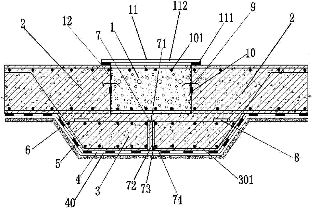
[0038] Such as figure 1 As shown, a basement basement advanced water-stop post-casting belt structure includes left and right basement floors 2 and a middle post-casting belt 1, and also includes a cast-in-place concrete trapezoidal groove structure 3 below the post-casting belt, and the basement floor 2 and the cast-in-place Below the concrete trapezoidal groove structure 3 are the waterproof membrane layer 4 , the waterproof coating layer 40 , the waterproof protective layer 5 and the concrete cushion 6 .

[0039] During specific implementation, the transverse reinforcement 301 of the cast-in-situ concrete trapezoidal groove structure 3 goes deep above the basement floor 2 on the left and right sides, and an expansion joint 7 is arranged in the middle of the trapezoidal groove structure 3, and an expansion joint 7 is provided at the junction end of the expansion joint 7 and the middle post-casting belt 1. U-shaped steel bars 71, with extruded polystyrene boards left inside, ...

Embodiment 2

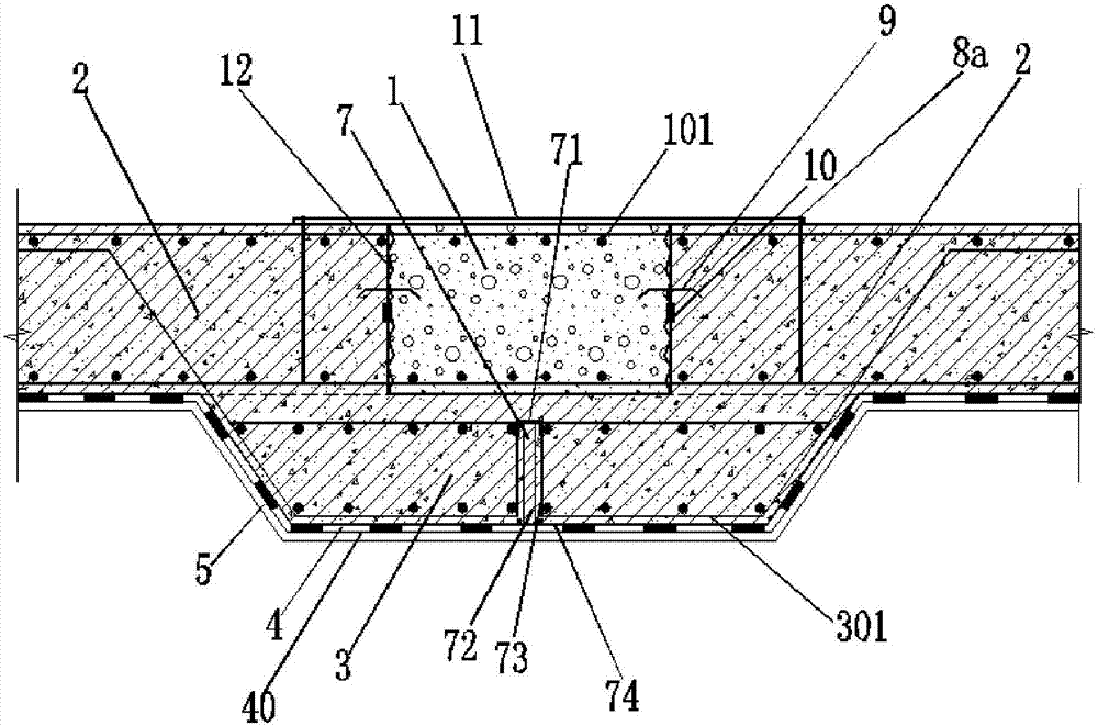
[0055] Such as figure 2 As shown, a basement side wall structure with advanced water-stop and post-casting belt, including left and right basement side walls 2 and a middle post-casting belt 1, also includes a cast-in-situ concrete trapezoidal groove structure 3 arranged under the post-casting belt, basement side wall 2 The outer side of the cast-in-place concrete trapezoidal groove structure 3 is a waterproof coiled material layer 4 , a waterproof coating layer 5 , and a waterproof protective layer 6 .

[0056] During specific implementation, the transverse steel bars 301 of the cast-in-place concrete trapezoidal groove structure 3 go deep into the inner sides of the basement side walls 2 on the left and right sides; There are U-shaped steel bars 71, and extruded polystyrene boards are left inside. After the concrete is poured, the joints are cleared, and then asphalt and linseed 72 are used to fill the joints. Both sides of the expansion joint 7 are equipped with external w...


PUM


Abstract

The invention discloses a post-cast strip structure for previously stopping water in basements and a construction method thereof. The structure comprises a main basement structure on the left and right sides, a post-cast strip area and a cast-in-place trapezoid concrete groove structure which is arranged below the post-cast strip area. A water-proof material rolling layer, a water-proof polyurethane coating film layer, a water-proof protective layer and a concrete cushion layer are sequentially arranged below the main basement structure and the cast-in-place trapezoid concrete groove structure; the post-cast strip structure for previously stopping the water in the basements has the advantages of being excellent in leaking-proof and water-proof effect, simple in structure, high in contraction distortion capability, and capable of effectively preventing sundries and accumulated water from entering the post-cast strip area, avoiding secondary cleaning, providing convenience for construction and effectively accelerating construction progress, and moreover, the undesirable phenomena such as slurry accumulation, water accumulation and the like are unlikely to occur by using the structure, so that the post-cast strip structure for previously stopping the water in the basements is worthy of popularization.

Description

technical field [0001] The invention relates to the field of construction engineering, in particular to a basement advanced water-stop and post-cast belt structure and a construction method thereof. Background technique [0002] Since the reform and opening up, especially in the past ten years, my country's social economy has developed rapidly, the construction scale has become increasingly grand, and the structural types have become more complex and diverse, especially the ultra-long and ultra-deep basement structures and the connection of high-rise main buildings with low-rise or multi-storey podium buildings There are many structural forms, which require the setting of a post-casting tape structure. At present, there are some post-casting and advanced water-stop constructions, but these advanced water-stopping constructions have problems such as easy leakage, cracks, slurry accumulation, water accumulation, uneven surface, poor flatness and debris cleaning in the post-cast...

Claims


Application Information

Patent Timeline
Patent Type & Authority Applications(China)
IPC IPC(8): E02D29/16
CPCE02D29/16
Inventor 卢士华梁环跃
Owner GUANGZHOU PANYU POLYTECHNIC
Why Eureka
Try Eureka