
Glue blocking device, blade and blade forming method

A blade and adhesive glue technology, applied in wind power generation, engine components, wind turbines, etc., can solve problems such as the inability of operators to enter the space to collect glue, the decline of blade performance, and the hidden dangers of wind power blade quality, so as to ensure production quality and The effect of service life

Pending Publication Date: 2019-10-29
SINOMATECH WIND POWER BLADE
View PDF0 Cites 0 Cited by
  • Summary
  • Abstract
  • Description
  • Claims
  • Application Information

AI Technical Summary

Problems solved by technology

After the wind turbine blades are molded and bonded, the adhesive in the bonding area will be squeezed by the shell on the windward side and the shell on the leeward side and overflow into the hollow space or out of the shell. At this time, the adhesive in the bonding area Gum shape can cause blade performance degradation during blade operation
[0003] At present, the main method is that the operator enters the interior of the blade shell to clean up the overflowing adhesive. However, due to the narrow space at the blade tip, the operator cannot enter the space to collect the glue, which will cause certain quality problems during the operation of the wind turbine blade.

Method used


Image

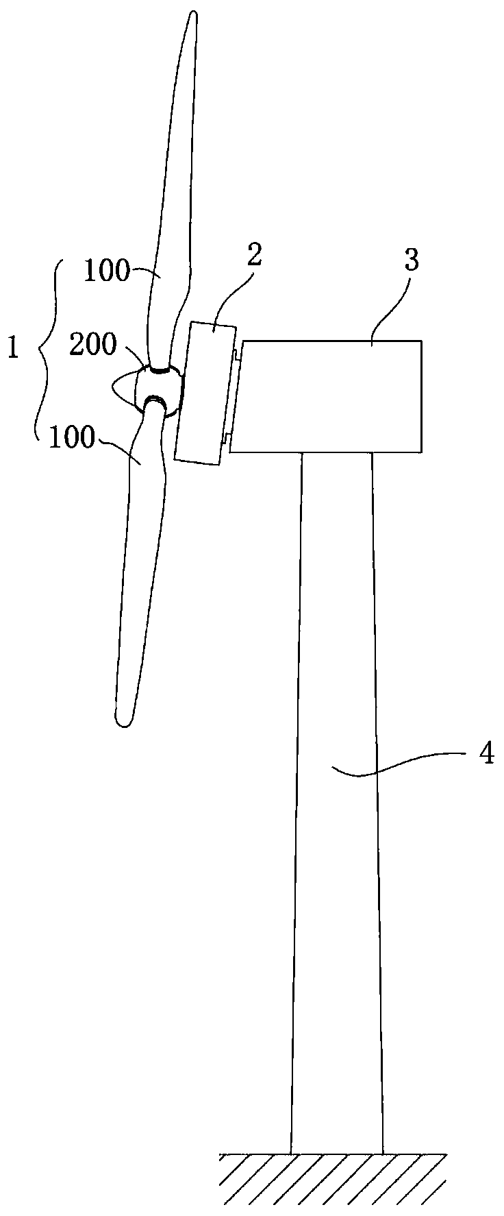
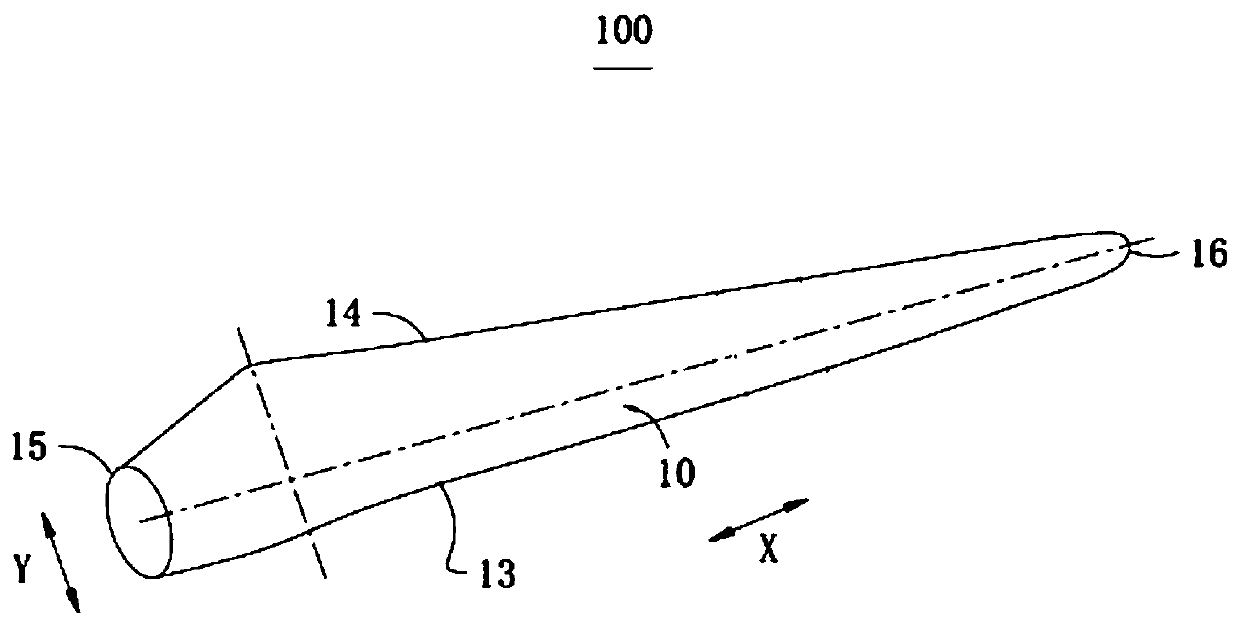
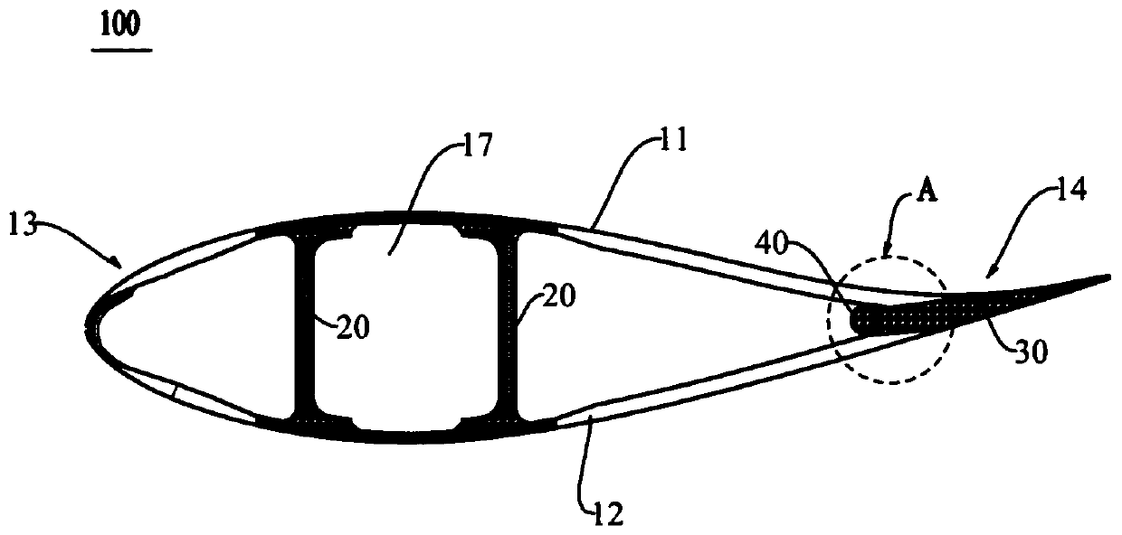
  • Glue blocking device, blade and blade forming method
  • Glue blocking device, blade and blade forming method
  • Glue blocking device, blade and blade forming method

Examples


Embodiment Construction

[0047] The features and exemplary embodiments of each aspect of the present invention will be described in detail below. In order to make the objectives, technical solutions, and advantages of the present invention clearer, the following further describes the present invention in detail with reference to the accompanying drawings and specific embodiments. It should be understood that the specific embodiments described herein are only configured to explain the present invention, for exemplarily explaining the principle of the present invention, and not configured to limit the present invention. In addition, the mechanical components in the drawings are not necessarily drawn to scale. For example, for other structural members or regions, the size of some structural members or regions in the drawings may be enlarged to help the understanding of the embodiments of the present invention.

[0048] The orientation words appearing in the following description are all directions shown in ...


PUM


Abstract

The invention discloses a glue blocking device, a blade and a blade forming method. The glue blocking device is used for the blade, the blade comprises a windward side shell and a leeward face shell which are oppositely arranged, an adhesive bonding layer is arranged between the rear edge area of the windward side shell and the rear edge area of the leeward face shell, the glue blocking device comprises a body, wherein the body is provided with a containing space and a first port communicating with the containing space, the containing space extends in the long axis direction of the body, the outer surface of the body comprises a protruding portion, the protruding portion protrudes to the part, away from the containing space, from the containing space, and the first port penetrates throughthe protruding portion; and the glue blocking device can be arranged in the hollow space and is connected with the windward side shell and the leeward surface shell through the body, the first port and the protruding portion are arranged towards the adhesive bonding layer, and at least a part of the adhesive bonding layer can be arranged in the containing space through the first port. According tothe glue blocking device, the blade and the blade forming method, the quality of blade and the operation stability of the blade can be improved.

Description

Technical field [0001] The invention relates to the technical field of wind power, in particular to a rubber stopper, a blade and a blade forming method. Background technique [0002] With the continuous development of wind power technology, it has become a development trend in the industry to provide more stable and more powerful wind turbines. Blades, as the key components of wind turbines, have also attracted more and more attention. After the wind turbine blades are mold-closed and bonded, the adhesive in the bonding area will be squeezed by the windward and leeward shells and overflow into the hollow space or out of the shell. At this time, the bonding area The rubber shape will cause the blade performance to decrease during the blade operation. [0003] At present, the main method is that the operator enters the blade shell to clean up the spilled adhesive. However, due to the narrow space of the blade tip, the operator cannot enter the space to collect the glue, which will ...

Claims


Application Information

Patent Timeline
IPC IPC(8): F03D1/06
CPCF03D1/0675F05B2230/20Y02E10/72
Inventor 赵立岩刘妍廉坤高国强陈淳
Owner SINOMATECH WIND POWER BLADE
Learn More