A connector crimping device

A crimping device and connector technology, which is applied in connection, test/measurement connectors, coupling devices, etc., can solve problems such as poor uniformity and traceability, many fixtures, and complicated processes, and achieve uniformity and Strong traceability, high consistency, and solve the effect of many fixtures

Active Publication Date: 2021-06-01
SHANGHAI NCATEST TECH CO LTD
View PDF6 Cites 0 Cited by
  • Summary
  • Abstract
  • Description
  • Claims
  • Application Information

AI Technical Summary

Problems solved by technology

[0003] However, using the existing manual crimping method, when installing different connectors on boards of different thicknesses, there are many fixtures and complex processes.
Moreover, manual operation is required during crimping, which is not only prone to errors, but also has problems of poor uniformity and traceability

Method used


Image

  • A connector crimping device
  • A connector crimping device

Examples


Embodiment Construction

[0022] The specific embodiment of the present invention will be further described in detail below in conjunction with the accompanying drawings.

[0023] It should be noted that, in the following specific embodiments, when describing the embodiments of the present invention in detail, in order to clearly show the structure of the present invention for the convenience of description, the structures in the drawings are not drawn according to the general scale, and are drawn Partial magnification, deformation and simplification are included, therefore, it should be avoided to be interpreted as a limitation of the present invention.

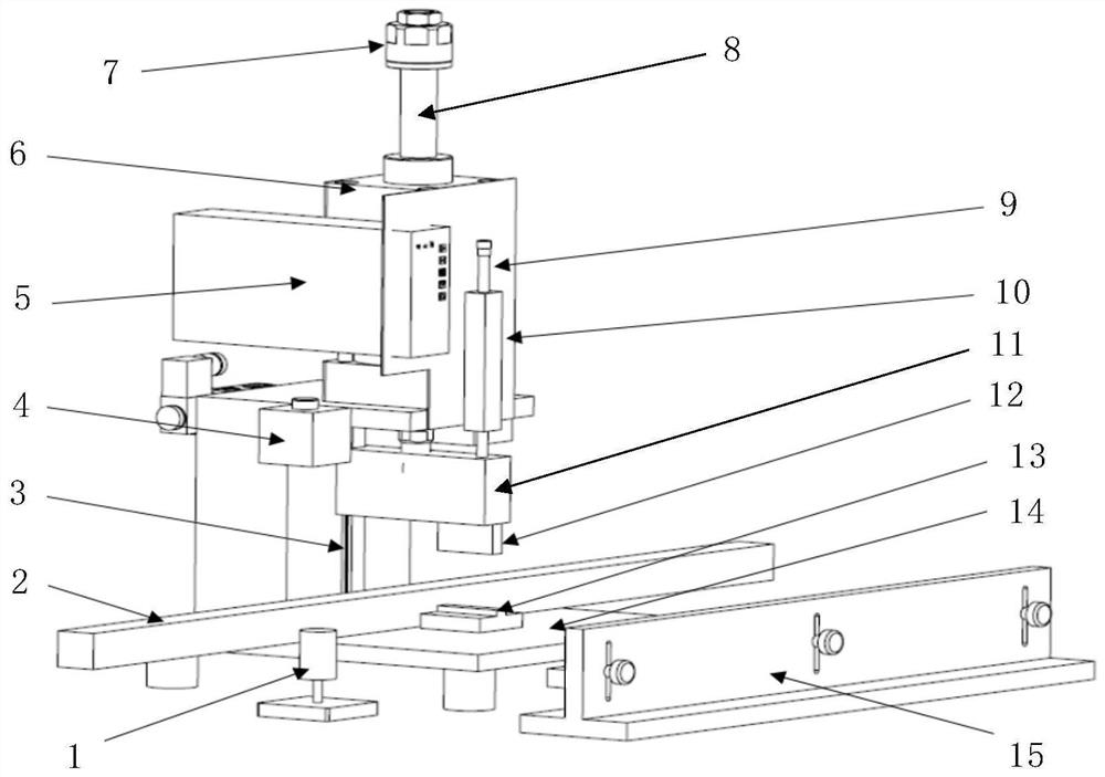
[0024] In the following specific embodiments of the present invention, please refer to figure 1 , figure 1 It is a structural schematic diagram of a connector crimping device according to a preferred embodiment of the present invention. Such as figure 1 As shown, a connector crimping device of the present invention includes: a pressing mechanism, ...


PUM


Abstract

The invention discloses a connector crimping device, comprising: a pressing mechanism, which provides a pressing force within a set stroke, and the pressing mechanism is provided with a pressing moving part; The thickness is set to the corresponding stroke of the pressing mechanism; the crimping mechanism includes an upper crimping needle block and a lower fixing seat, the lower end of the upper crimping needle block is provided with a pressing needle, and the upper crimping needle block It is arranged at the lower end of the press-down moving part, and is used for driving the press-down moving part to pass through the fixing pin on the connector of the board card positioned on the lower fixing seat below the pressing pin Make a crimp. The invention can well meet the requirements of the same equipment for crimping connectors of various specifications, and at the same time can realize semi-automatic and controllable operation, and has very high consistency and traceability.

Description

technical field [0001] The invention relates to the technical field of semiconductor testing, and more particularly, to a semi-automatic crimping device for a board connector. Background technique [0002] In the existing testing field, the installation technology of the card connector is mainly through manual crimping. Moreover, for boards and connectors of different thicknesses, it is necessary to adjust the auxiliary fixture module to achieve accurate crimping. [0003] However, when using the existing manual crimping method, when installing different connectors on boards of different thicknesses, there are many fixtures and complex processes. Moreover, manual operation is required during crimping, which is not only prone to errors, but also has problems of poor uniformity and traceability. Contents of the invention [0004] The object of the present invention is to overcome the above-mentioned defects in the prior art and provide a connector crimping device. [0005...

Claims


Application Information

Patent Timeline
Patent Type & Authority Patents(China)
IPC IPC(8): H01R43/00H01R43/048B23P19/027H01R12/71
CPCB23P19/027H01R12/716H01R43/00H01R43/048H01R2201/20
Inventor 赵剑
Owner SHANGHAI NCATEST TECH CO LTD
Why Eureka
Try Eureka