
Spinning type current-splitting wire clamp

A shunt line and splint technology, applied in the direction of the cable suspension device, etc., can solve the problems that affect the safe and reliable operation of the transmission line, loose connection bolts of the diversion plate, poor contact of the diversion plate, etc., and achieve good practical use and promotion value, structure Simple and practical design, time-saving and labor-saving installation

Inactive Publication Date: 2019-10-29
国网湖北省电力有限公司黄石供电公司
View PDF0 Cites 0 Cited by
  • Summary
  • Abstract
  • Description
  • Claims
  • Application Information

AI Technical Summary

Problems solved by technology

[0002] Since the transmission lines are exposed to the open field all the year round, external force vibration and construction technology problems can easily cause the connecting bolts of the drainage plate to loosen, resulting in poor contact of the drainage plate and overheating of the wire clamp. Long-term overheating operation will cause burns and deformation of the strain-resistant clamp, causing wire Damage, broken strands, etc., if not dealt with in time, will eventually lead to wire breakage, affecting the safe and reliable operation of transmission lines

Method used


Image

  • Spinning type current-splitting wire clamp
  • Spinning type current-splitting wire clamp

Examples


Embodiment Construction

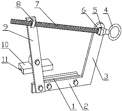
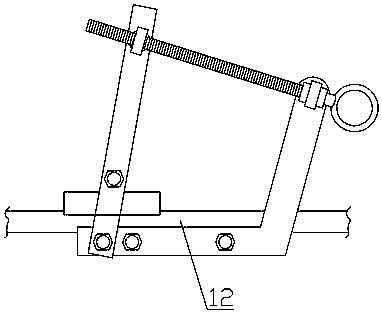
[0014] see figure 1 , figure 2 , the present invention is a spinning type shunt clamp, which has an L-shaped mounting plate, the L-shaped mounting plate is composed of a horizontal plate 2 and a slanting plate 3, and a lower splint is fixed on the rear side of the horizontal plate 1. There is a cable groove on the lower splint, a rotating connecting plate 9 is hinged on the front side of the horizontal plate, and a rotating threaded collar 8 is provided on the upper front side of the rotating connecting plate; the inclined plate A rotating non-threaded collar 5 is arranged on the upper front side of the upper part, and an adjusting screw 7 is installed between the rotating threaded collar and the rotating non-threaded collar. The collar is idlingly connected, and the adjustment screw is provided with an adjustment handle 4 at one end of the rotating non-threaded collar, and an idling limit block 6 is also provided on the two sides of the rotating non-threaded collar on the a...


PUM


Abstract

The invention relates to a spinning type current-splitting wire clamp. The clamp includes an L-shaped installation plate, the L-shaped installation plate is composed of a transverse plate and an inclined plate, a lower clamping plate is fixedly disposed on the rear side of the transverse plate, a cable groove is disposed on the lower clamping plate, a rotation connection plate is hinged to the front side of the transverse plate, and a rotation threaded sleeve ring is disposed on the front side surface of the upper portion of the rotation connection plate; a rotation non-threaded sleeve ring isdisposed on the front side surface of the upper portion of the inclined plate, an adjustment screw rod is installed between the rotation threaded sleeve ring and the rotation non-threaded sleeve ring, an adjustment handle is disposed on one end of the adjustment screw rod located at the rotation non-threaded sleeve ring, and an idle running limit stopping block is further disposed on both sides of the adjustment screw rod located on the rotation non-threaded sleeve ring; an upper clamping plate is rotatably connected to the middle portion of the rotation connection plate, the bottom of the upper clamping plate is also provided with the cable groove, and the cable grooves of the upper clamping plate and the lower clamping plate together form clamping to a cable; and the clamp is simple andpractical in structural design, is good in usage effect, and has good practical usage and popularization value.

Description

technical field [0001] The invention relates to the technical field of power transmission line operating equipment, in particular to a spinning type shunt clamp. Background technique [0002] Since the transmission lines are exposed to the open field all the year round, external force vibration and construction technology problems can easily cause the connecting bolts of the drainage plate to loosen, resulting in poor contact of the drainage plate and overheating of the wire clamp. Long-term overheating operation will cause burns and deformation of the strain-resistant clamp, causing wire Damage, broken strands, etc., if not dealt with in time, will eventually lead to wire breakage and affect the safe and reliable operation of the transmission line. Contents of the invention [0003] The purpose of the present invention is to solve the above-mentioned problems in the actual use of the traditional wire drainage plate, and provide a spinning type shunt clamp with wide applic...

Claims


Application Information

Patent Timeline
Patent Type & Authority Applications(China)
IPC IPC(8): H02G7/05
CPCH02G7/05
Inventor 谢志刚蔡杰张再华陈超肖勇武志超王江涛尹鹏飞叶俊郭攀陈睿朱世灿
Owner 国网湖北省电力有限公司黄石供电公司
Learn More