Method and device for triggering focusing of camera equipment

A technology of camera equipment and focus detection, applied in the field of optical imaging, can solve problems such as blurred focus scenes, slow changes in image operator values ​​that are difficult to accurately identify, focus and defocus, etc., to achieve the effect of avoiding focus and defocus

Active Publication Date: 2019-10-29
ZHEJIANG DAHUA TECH
View PDF9 Cites 2 Cited by
  • Summary
  • Abstract
  • Description
  • Claims
  • Application Information

AI Technical Summary

Problems solved by technology

[0006] The present invention provides a method and device for triggering the focusing of camera equipment, which is used to solve the problem that it is difficult to accurately identify slowly changing scenes when the monitoring equipment automatically focuses, that is, when the image operator value changes slowly
Causes the focus to be out of focus during the auto focus process, and the actual focus scene is blurred after the scene is clear

Method used


Image

  • Method and device for triggering focusing of camera equipment
  • Method and device for triggering focusing of camera equipment
  • Method and device for triggering focusing of camera equipment

Examples


Embodiment 1

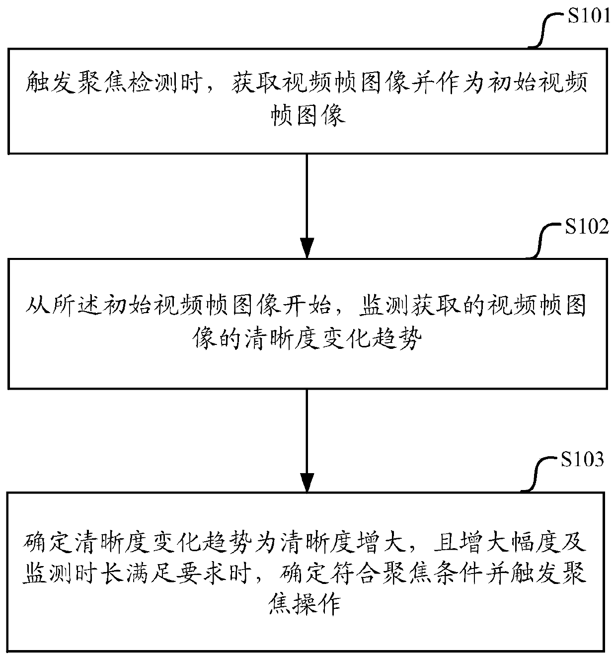
[0053] At present, the automatic focus of the monitoring equipment encounters the scene where the operator value changes slowly, which will lead to focusing failure. However, because the image operator value of the monitoring equipment shows a trend of rising slowly during the fog dissipation process, the scene has outline details when the fog completely dissipates. For this Features The present invention provides a method of triggering the focus of the camera device, such as figure 1 shown, including:

[0054] Step S101, when triggering focus detection, acquire a video frame image and use it as an initial video frame image;

[0055] In this embodiment, the camera device can be used as a monitoring device, and the monitoring device can be set to auto focus. When the above-mentioned trigger focus detection is auto focus, the focus detection is triggered. When the monitoring device detects manual focus, the focus detection is not triggered.

[0056] It can be determined but not...

Embodiment 2

[0104] A method for triggering the focus of the imaging device in the present invention has been described above, and an apparatus for executing the above-mentioned triggering of the focus of the imaging device will be described below.

[0105] see image 3 An embodiment of the present invention provides an apparatus for triggering the focusing of an imaging device, including:

[0106] An image acquisition module 301, configured to acquire a video frame image as an initial video frame image when triggering focus detection;

[0107] An image processing module 302, configured to start from the initial video frame image, and monitor the definition change trend of the acquired video frame image;

[0108] The trigger focusing module 303 is configured to determine that the sharpness change trend is an increase in sharpness, and when the increase range and the change time range meet the requirements, determine that the focusing condition is met and trigger the focusing operation.

...


PUM


Abstract

The invention discloses a method and device for triggering focusing of camera equipment, and the device comprises the steps: obtaining a video frame image as an initial video frame image when the focusing detection is triggered; starting from the initial video frame image, monitoring the definition change trend of the obtained video frame image; and when determining that the definition change trend is definition increase and the increase amplitude and the monitoring duration meet the requirements, determining that the focusing condition is met and triggering the focusing operation. According to the method, the slowly changing scene, namely the operator value of the image, can be effectively recognized, and the problems of focusing defocusing in the automatic focusing process and actual focusing scene blurring after the scene is clear are avoided. And the monitoring equipment can focus when the image is clear.

Description

technical field [0001] The invention relates to the technical field of optical imaging, in particular to a method and device for triggering the focusing of an imaging device. Background technique [0002] The security industry monitoring system acquires imaging systems in other systems to obtain clear images only on the basis of accurate focused imaging, which provides conditions for subsequent processing. Autofocus is to use software and hardware conditions to analyze and judge the collected images, evaluate the clarity of the images and feed back the information to the front-end drive device of the lens to drive the lens position, so as to finally capture the best image. [0003] Auto-focus technology is widely used in various precision instruments such as cameras and video cameras. Since the content of the video sequence scene captured by the camera changes, the interference caused by the scene change to the focusing process will cause the focus to fail. The auto-focus al...

Claims


Application Information

Patent Timeline
IPC IPC(8): H04N5/232
CPCH04N23/67H04N23/667
Inventor 虞卫勇赵军刘峰明刘春龙夏瑞
Owner ZHEJIANG DAHUA TECH
Why Eureka
Try Eureka