
Camera focus control device

A lens and frame technology, applied in the lens field, can solve problems such as lack of precision fine-tuning, difficult cam structure, and inability to meet focus adjustment requirements, and achieve the effects of reducing labor intensity, simple and convenient assembly, and reducing the probability of assembly errors

Pending Publication Date: 2018-11-23
XIAMEN LEADING OPTICS
View PDF7 Cites 0 Cited by
  • Summary
  • Abstract
  • Description
  • Claims
  • Application Information

AI Technical Summary

Problems solved by technology

However, the cam structure is difficult to meet the needs of precision fine-tuning lens
For example, it cannot meet the focus adjustment requirements: the adjustment ring of the frame rotates 360° so that the frame only has a displacement of 0.5mm or even less relative to the main barrel, which does not meet the requirements of precise fine-tuning

Method used


Image

  • Camera focus control device
  • Camera focus control device
  • Camera focus control device

Examples


Embodiment 1

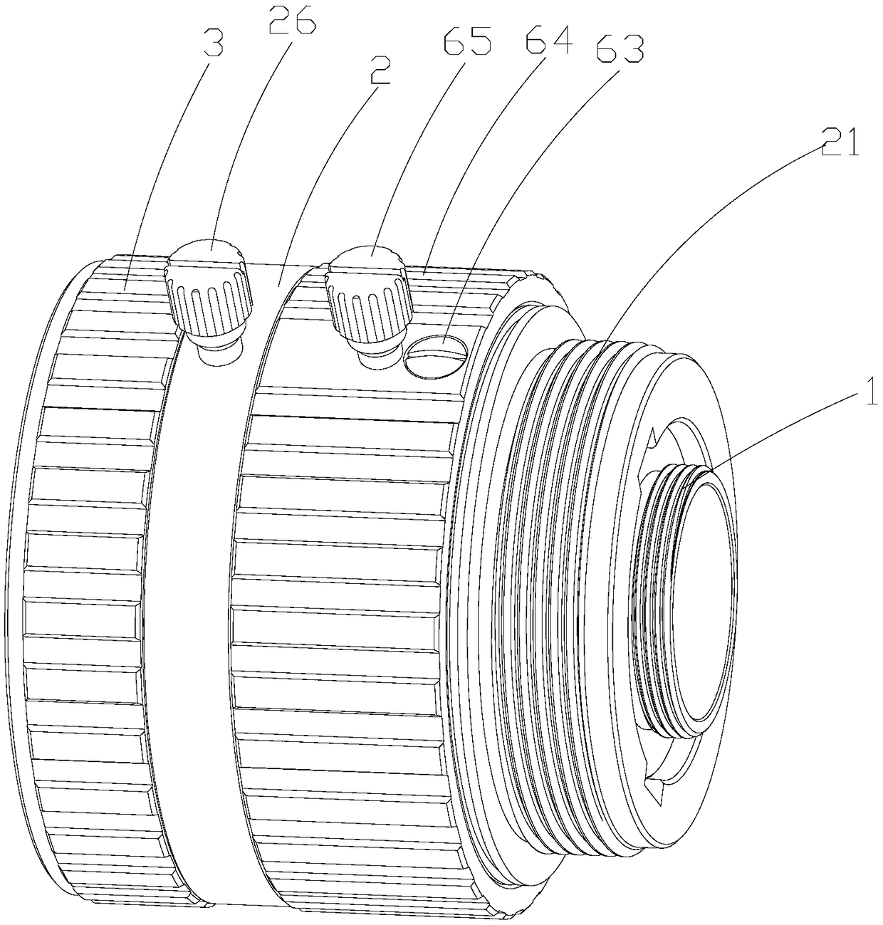
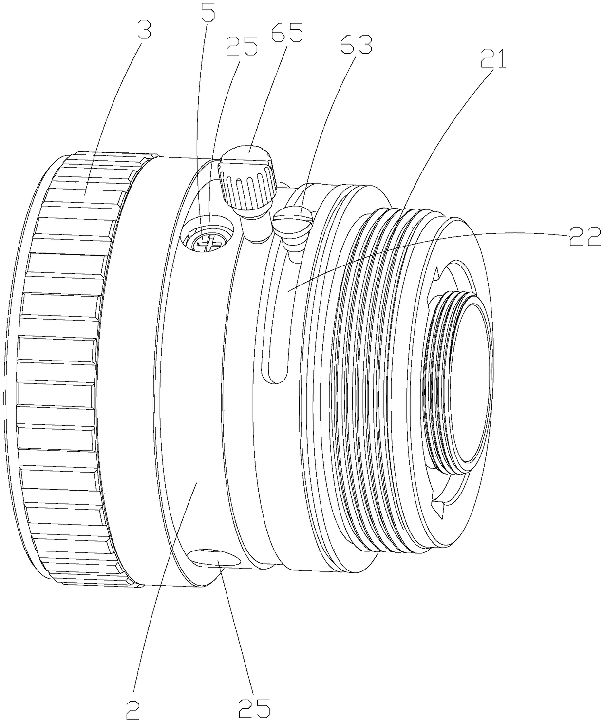
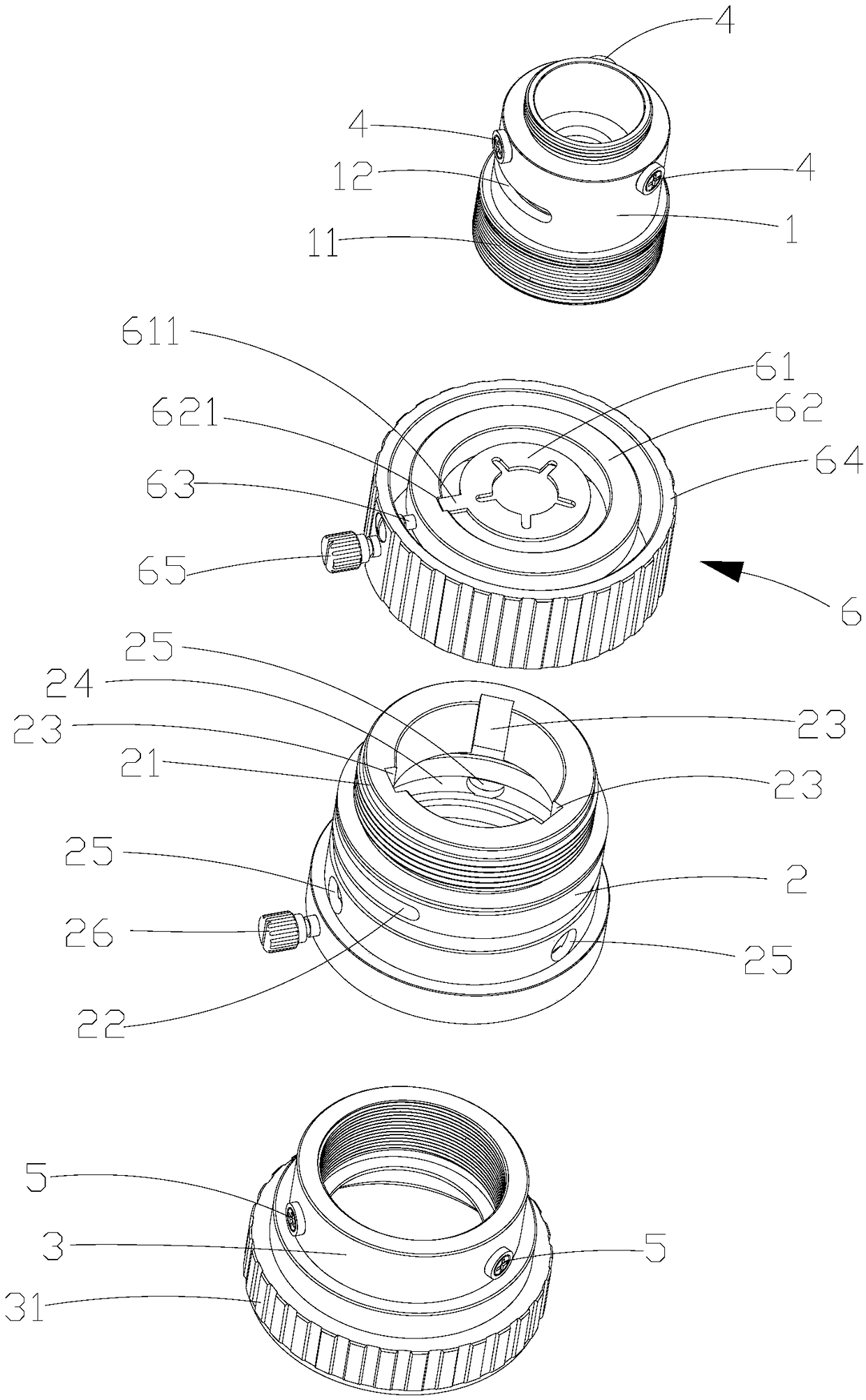
[0036] Please refer to attached figure 1 to attach Figure 6 , in an embodiment of the present invention, a lens focusing device includes a frame 1, a main barrel 2 and a frame adjustment ring 3, a frame threaded portion 11 is provided on the outer periphery of the front end of the frame 1, and the frame 1 is adjusted with the frame through the threaded portion 11 of the frame. The ring 3 is threaded, the frame 1 and the frame adjusting ring 3 are set in the main tube 2, and the frame 1 and the main tube 2 are restricted by the first stopper 4 between the frame 1 and the main tube 2 to move back and forth in the axial direction relative to the main tube 2 Instead of being able to rotate in the circumferential direction relative to the main cylinder 2, the frame adjustment ring 3 and the main cylinder 2 are restricted by the second limiter 5 between the frame adjustment ring 3 and the main cylinder 2. To move back and forth, the outer circumference of the end of the main cylin...

Embodiment 2

[0049] The difference between this embodiment and Embodiment 1 is that in this embodiment, the first limiting member 4 is connected and arranged on the inner surface of the main cylinder 2, and the mirror frame 1 is provided with an axial straight line that matches the first limiting member 4. The first stopper 4 restricts the mirror frame 1 to only move back and forth relative to the main cylinder 2 along the axial straight groove but not to rotate circumferentially relative to the main cylinder 2 .


PUM


Abstract

The present invention discloses a camera focus control device. The camera focus control device comprises a camera frame, a main tube and a camera frame regulation ring, a camera frame screw thread portion is arranged at the periphery of the front end of the camera frame, the camera frame is in threaded connection with the camera frame regulation ring through the camera frame screw thread portion,the camera frame and the camera frame regulation ring sleeve the internal portion of the main tube, a first stop piece is arranged between the camera frame and the main tube to restrict the camera frame to move back and forth only relative to the main tube in an axial direction, a second stop piece is arranged between the camera frame regulation ring and the main tube to restrict the camera frameregulation ring to rotate in a circumference only relative to the main tube, a main tube screw thread portion is arranged at the periphery of the tail end of the main tube, the main tube is in threaded connection with a camera adapter ring through the main tube screw thread portion, when focus is regulated, the main tube keeps still relative to the camera adapter ring, and the camera frame regulation ring is employed to allow the camera frame to move back and forth in an axial direction relative to the main tube to regulate the focus. The camera focus control device is compact in structure andsimple, convenient and rapid in assembling, reduces the manufacturing cost and is convenient and stable in focus control, and a threaded pitch between the camera frame regulation ring and the cameraframe can be flexibly selected according to an actual demand.

Description

technical field [0001] The invention relates to the field of lens technology, in particular to a lens focusing device. Background technique [0002] In the existing lens focusing structure with a brace mechanism, the main barrel, the brace, and the frame are threaded. During the focusing process, the brace is rotated to make it move axially relative to the main barrel. Due to the rotation and axial movement of the braces, it will drive the axial movement of the mirror frame, and then achieve the purpose of focusing. However, the thread fit between the braces, the main barrel and the mirror frame needs to be controlled and screwed smoothly without shaking, and the processing difficulty is high. In addition, during the focusing process, the braces will be displaced relative to the main barrel, and the essence of the effective movement of the focus is that the mirror frame and The main barrel is displaced. Brace movement will affect the focusing process, and this part of the ...

Claims


Application Information

Patent Timeline
IPC IPC(8): G02B7/04G02B7/02G02B7/00
CPCG02B7/00G02B7/022G02B7/04
Inventor 吴富宝蔡冬波
Owner XIAMEN LEADING OPTICS
Learn More