Prosthetic knee with a rectification hydraulic system

A technology of prosthetics and ports, applied in the field of prosthetic knee joints with a corrected hydraulic system, can solve the problems that the hydraulic system affects the performance and cost of prosthetics

Inactive Publication Date: 2019-10-29
宝泰欧美国有限责任公司
View PDF13 Cites 1 Cited by
  • Summary
  • Abstract
  • Description
  • Claims
  • Application Information

AI Technical Summary

Problems solved by technology

The size and complexity of the hydraulic system also affects prosthetic performance and cost
Therefore, additional prosthetic devices may be required

Method used


Image

  • Prosthetic knee with a rectification hydraulic system
  • Prosthetic knee with a rectification hydraulic system
  • Prosthetic knee with a rectification hydraulic system

Examples


Embodiment Construction

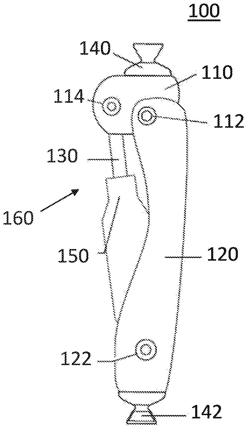
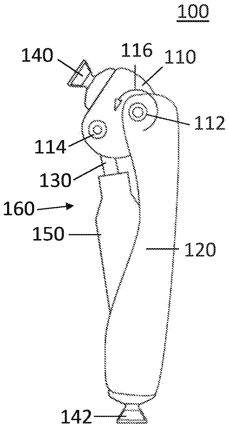
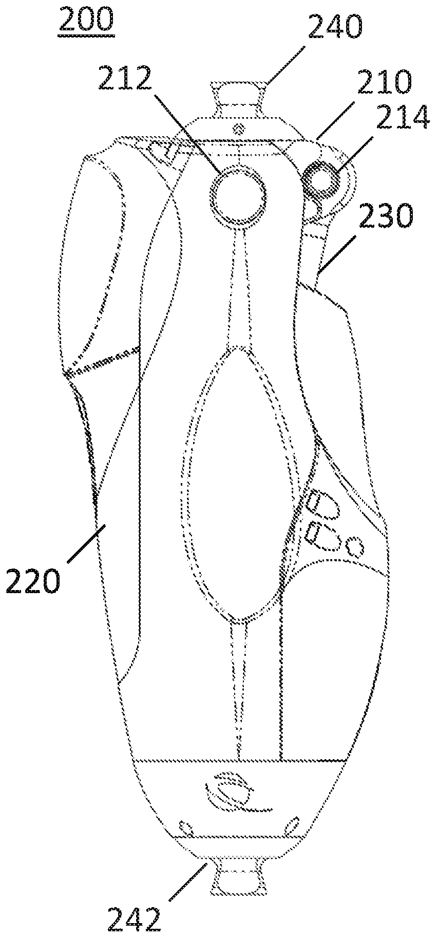
[0033] Described herein are hydraulic components, prosthetic systems, and methods for controlling hydraulic components or prosthetics. A microprocessor may be used to control a prosthetic joint as described herein to adjust the resistance of the joint based on the user's gait phase. In variations where the prosthetic joint includes a hydraulic system including a hydraulic cylinder and piston, the microprocessor may be configured to adjust the hydraulic fluid control valve to set the resistance of the hydraulic fluid through the hydraulic system for different phases of the gait cycle. In some variations, the hydraulic system may include components (eg, valves, fluid passages) to set the resistance of hydraulic fluid through the hydraulic system during power loss for different dynamic phases.

[0034] I. System

[0035] A. Prosthetic knee joint

[0036] Described here is a prosthetic used by amputees. In some variations, the prosthetic joints shown herein may be configured as p...


PUM


Abstract

Described here are prosthetic systems, devices, and methods of use therefor. Generally, a prosthesis may be configured to set a resistance to rotation of a prosthetic joint based on a phase of gait. The prosthesis may include a first cylinder, a first piston slidable within the first cylinder, a fluid sump, and a fluid circuit. The fluid circuit may include a plurality of interconnected fluid channels having a unidirectional variable-resistance valve and a set of check valves that are configured to provide unidirectional flow through the valve during piston compression and extension.

Description

[0001] Cross References to Related Applications [0002] This application claims priority to US Provisional Application No. 62 / 466,305, filed March 2, 2017, the contents of which are hereby incorporated by reference in their entirety. technical field [0003] The systems and methods herein relate to prosthetics with hydraulic damping systems, including but not limited to prosthetic knees and ankles. Background technique [0004] Prosthetics are designed to replace body parts that may be missing due to trauma, disease, or congenital conditions. There are ongoing efforts to develop prosthetics such as prosthetic knees with more natural gait or function. Some prosthetic knee joints include a hydraulic system to control the rotation of a rotor coupled to the lower leg member about the knee joint. Some hydraulic systems include hydraulic cylinders, pistons, hydraulic fluid, and hydraulic circuits having hydraulic fluid passages and valves for controlling the resistance of the h...

Claims


Application Information

Patent Timeline
Patent Type & Authority Applications(China)
IPC IPC(8): A61F2/50A61F2/68A61F2/70
CPCA61F2/64A61F2/6607A61F2/70A61F2002/5006A61F2002/704A61F2002/7635A61F2002/764A61F2002/7645A61F2002/7655A61F2002/7665A61F2/741A61F2/74A61F2/748A61F2/68
Inventor S·W·普林斯J·M·拜尔斯R·M·格利登四世H·A·昆特罗M·L·帕尔默
Owner 宝泰欧美国有限责任公司
Why Eureka
Try Eureka