Adjusting type automatic positioning device for bottle blowing machine

An automatic positioning and adjustment technology, which is applied in the direction of household components, household appliances, and other household appliances, can solve the problems of multi-standard product positioning and unreasonable structure, non-adjustable positioning position, inaccurate positioning, etc., and achieve simple and reasonable structure , wide application range, accurate positioning effect

Pending Publication Date: 2019-11-01
广东衡钢机械有限公司
View PDF2 Cites 0 Cited by
  • Summary
  • Abstract
  • Description
  • Claims
  • Application Information

AI Technical Summary

Problems solved by technology

[0004] The purpose of the present invention is to solve the problems of the existing positioning mechanism for bottle blowing machines, such as non-adjustable positioning position, unsuitable positioning for multi-standard products, unreasonable structure, inaccurate positioning and narrow application range, etc., to provide a bottle blowing machine. Machine adjustable automatic positioning device

Method used


Image

  • Adjusting type automatic positioning device for bottle blowing machine
  • Adjusting type automatic positioning device for bottle blowing machine
  • Adjusting type automatic positioning device for bottle blowing machine

Examples


specific Embodiment 1

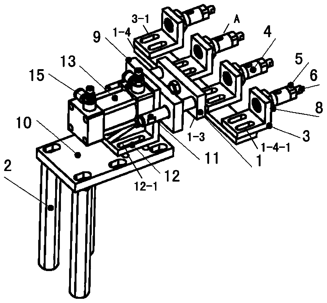
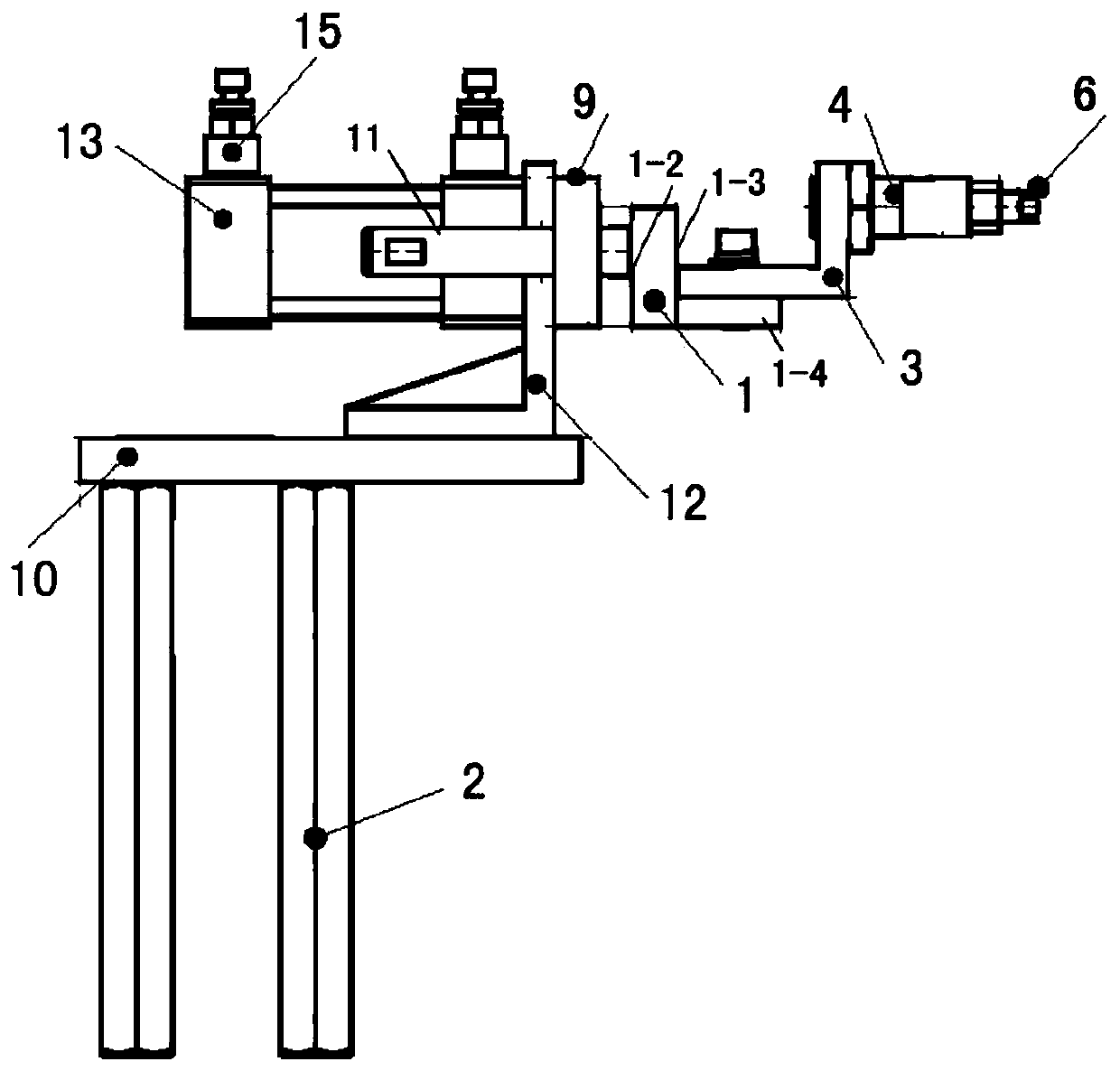
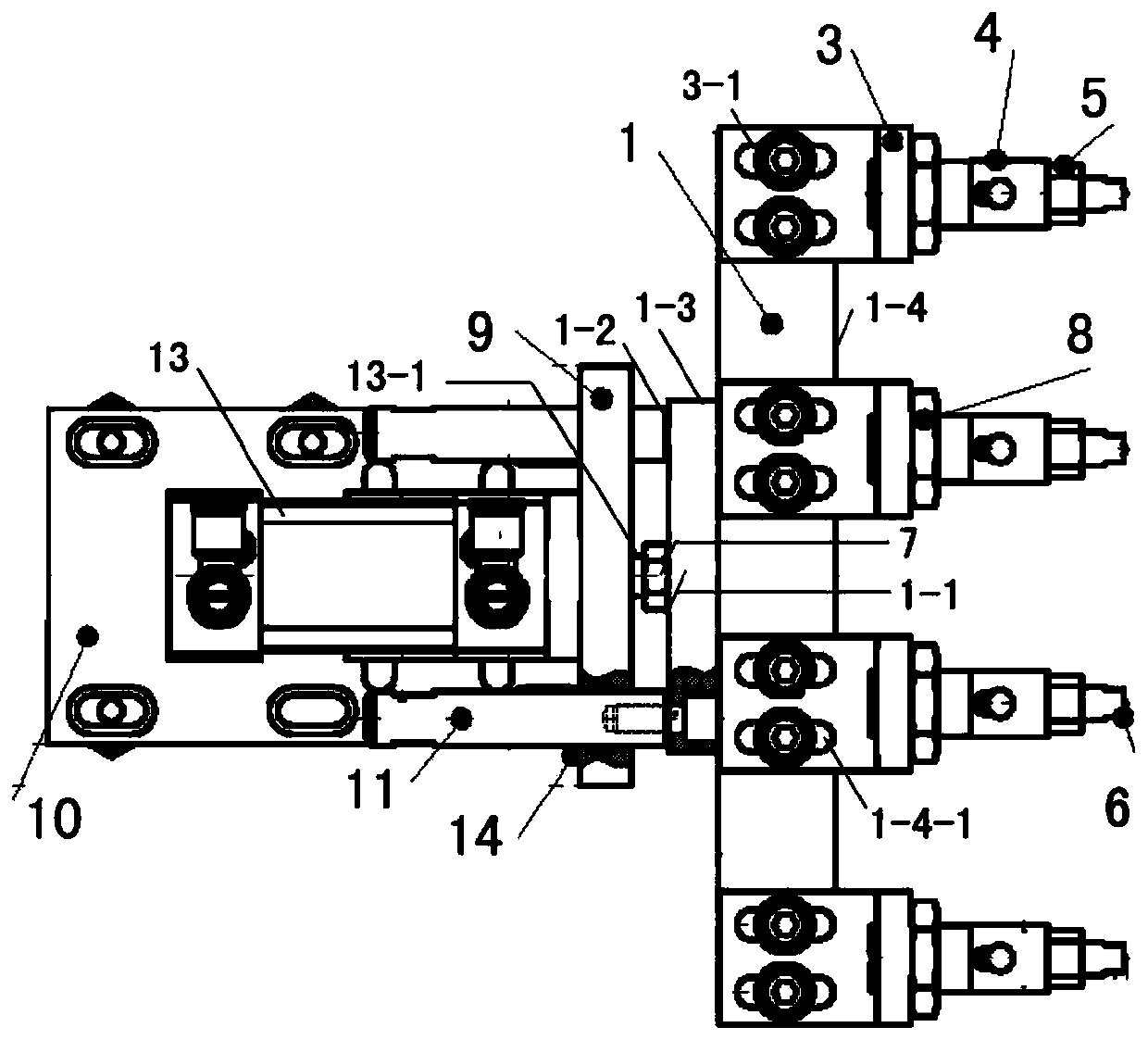
[0026] figure 1 to image 3 Constitute a specific embodiment of the present invention.

[0027] refer to Figure 1 to Figure 3 , the present embodiment includes a support seat 2, a support plate 10, a guide plate 9, a cylinder 13 and a control signal input end, the support plate 10 is arranged on the support seat 2, the cylinder 13 is arranged on the support plate 10, and a positioning adjustment member 1 is also included , the front end of the positioning adjustment member 1 is provided with a screw connection port 1-1 and a support connection end 1-2, the screw connection port 1-1 is the power input end of the positioning adjustment member 1 and is used to connect the piston rod 13 of the cylinder 13 -1, the support connecting end 1-2 is used to connect the guide rod 11 and constitute the sliding support structure of the positioning adjustment part; There is a front and rear position adjustment connection structure to adjust the relative position between the two, which co...

specific Embodiment 2

[0039] The characteristic of the specific embodiment 2 of the present invention is that two, three, five or six to ten positioners A are connected to the positioning adjustment member 1 . All the other are with specific embodiment 1.


PUM


Abstract

The invention relates to an adjusting type automatic positioning device for a bottle blowing machine. The automatic positioning device comprises a supporting base, a supporting plate, a guide plate, an air cylinder and a control signal input end, the automatic positioning device is characterized by further comprising a positioning adjusting part, wherein the front end of the positioning adjustingpart is provided with a screw joint end opening and a supporting connection end, the screw joint end opening is used for connecting with a piston rod of the air cylinder, and the supporting connectionend is used for connecting with a guide rod to form a sliding support structure of the positioning adjusting part; the rear end of the positioning adjusting part is connected with a positioner, a front and back position adjusting connecting structure is arranged at the joint of the positioning adjusting part and the positioner to form one of front and back position adjusting structures, and the piston rod is connected with the screw joint end opening through an adjusting nut to form the second of the front and back adjusting structures; the guide rod penetrates through the guide plate to be connected with the supporting connection end, and the guide plate is fixed on a cylinder body of the cylinder; and a control input end communicates with a cylinder control input end to form an adjusting type automatic positioning structure. The adjusting type automatic positioning device for the bottle blowing machine has the characteristics of being adjustable in positioning position, applicable to multi-specification product positioning, wide in application range and the like.

Description

technical field [0001] The invention relates to a blow molding machine positioning device, in particular to an adjustable automatic positioning device for a blow molding machine, which is widely applicable to PP blow molding machines or PET blow molding machines of various specifications. It belongs to the technical field of equipment for blowing plastic containers from preforms. Background technique [0002] The equipment that blows plastic containers from preforms is commonly known as blow molding machine. Generally speaking, a plurality of manipulators that rotate with the support turntable are installed on the ring-shaped support turntable of the rotary blow molding machine. , the positioning mechanism is installed on the ring-shaped support turntable; when the positioning mechanism rotates with the support turntable, it can drive the clamping part installed on it to move radially and rotate on the support turntable, so as to complete the delivery of bottles at the pred...

Claims


Application Information

Patent Timeline
Patent Type & Authority Applications(China)
IPC IPC(8): B29C49/42
CPCB29C49/4205B29L2031/7158
Inventor 温振明
Owner 广东衡钢机械有限公司
Why Eureka
Try Eureka