
Novel wire-type crank structure

A crank and line type technology, applied in the field of new linear crank crank structure, can solve the problem that the brake wire cannot completely fall into the wire pressing groove, easy to produce sliding wire, easy to press and break the brake wire and so on.

Pending Publication Date: 2019-11-01
KARASAWA TRAFFIC EQUIP TAIZHOU
View PDF0 Cites 0 Cited by
  • Summary
  • Abstract
  • Description
  • Claims
  • Application Information

AI Technical Summary

Problems solved by technology

[0002] At present, the structure design of the existing linear crank throws is unreasonable. The pressure groove is set on the body of the linear crank throw. The brake wire cannot be completely dropped into the wire groove, and the brake wire is easily broken. generate slip line

Method used


Image

  • Novel wire-type crank structure
  • Novel wire-type crank structure
  • Novel wire-type crank structure

Examples


Embodiment Construction

[0012] The present invention will be further explained below in conjunction with the accompanying drawings and embodiments.

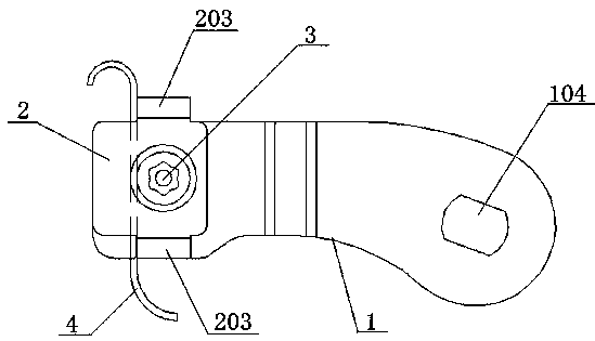
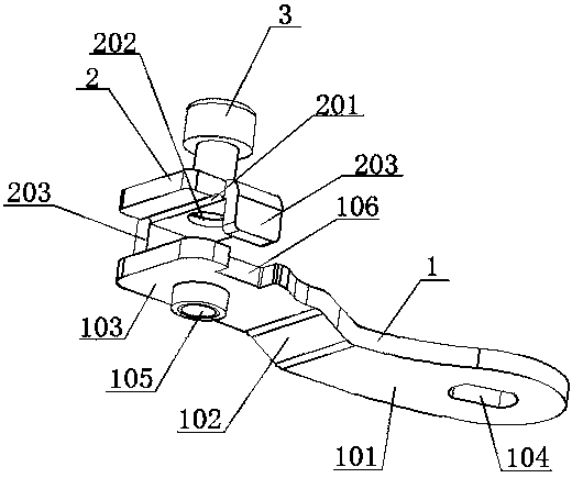
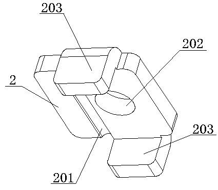
[0013] like Figure 1-Figure 3 As shown, a novel line bellcrank structure includes a line bellcrank body 1, a pressure plate 2 and an anti-theft bolt 3. The brake line positioning plate 103 constitutes an integral part, and one end of the crank throw body plane plate 101 is connected to the brake line positioning plate 103 through a shaped curved plate 102, and the other end of the crank throw body plane plate 101 is provided with a camshaft mounting hole 104, so that The brake wire positioning plate 103 is provided with a first threaded hole 105 compatible with the anti-theft bolt, and the pressure plate 2 is provided with a crimping groove 201 and a second threaded hole 202 adapted with the anti-theft bolt, and Limiting flanges 203 are provided on both sides of the wire crimping plate 2, the crimping groove 201 is located at one side of the limiting ...


PUM


Abstract

The invention discloses a novel wire-type crank structure. The structure comprises a wire-type crank body (1), a wire pressing plate (2) and an anti-theft bolt (3), wherein the wire-type crank body iscomposed of a crank body flat plate (101), a forming curved plate (102) and a brake cable positioning plate (103), one end of the crank body flat plate is connected with the brake cable positioning plate through the forming curved plate, a cam shaft mounting hole (104) is formed in the other end of the crank body flat plate, a first threaded hole (105) matched with the anti-theft bolt is formed in the brake cable positioning plate, a wire pressing groove (201) and a second threaded hole (202) which is matched with the anti-theft bolt are formed in the wire pressing plate, limiting flanges (203) are arranged on the two sides of the wire pressing plate respectively, a receding groove (106) is formed in one side of the brake cable positioning plate, and the limiting flange on one side of thewire pressing plate is matched and clamped with the receding groove. According to the structure, a brake cable can be completely installed in the wire pressing groove, the brake cable cannot be broken easily, the brake cable is limited by limiting flanges arranged on the two sides of the wire pressing plate, and the sliding wire is not easy to generate.

Description

technical field [0001] The invention relates to the technical field of brake accessories, in particular to a novel linear bellcrank structure. Background technique [0002] At present, the structure design of the existing linear crank throw is unreasonable. The pressure groove is set on the body of the linear crank throw. Generate slides. Therefore, those skilled in the art are badly in need of researching out a kind of novel linear bellcrank structure. Contents of the invention [0003] The object of the present invention is to provide a novel linear crank throw structure in order to solve the above-mentioned deficiencies in the prior art. [0004] In order to achieve the above-mentioned purpose of the invention, the technical solution provided by the present invention is as follows: a novel linear crank throw structure, including a linear crank throw body, a pressure plate and an anti-theft bolt, the linear crank throw body is composed of a crank throw body plane plate...

Claims


Application Information

Patent Timeline
Patent Type & Authority Applications(China)
IPC IPC(8): B62L3/02F16C1/10
CPCB62L3/02F16C1/10
Inventor 孙浙勇唐文贵曹玉荣周文青
Owner KARASAWA TRAFFIC EQUIP TAIZHOU
Learn More