Non-pressure grouting method based on mine construction

A grouting and mine technology, applied in mining equipment, shaft equipment, shaft lining, etc., can solve the problems of broken surrounding rock, a small amount of water gushing, and poor quality of the shaft wall, so as to reduce the pressure of the shaft wall and ensure the quality of the shaft wall quality effect

Active Publication Date: 2020-09-18
CHINA COAL NO 3 CONSTR GRP
View PDF8 Cites 0 Cited by
  • Summary
  • Abstract
  • Description
  • Claims
  • Application Information

AI Technical Summary

Problems solved by technology

[0002] In mine construction (shaft and roadway), it is often encountered that the surrounding rock is relatively broken or there is a small amount of water gushing. Although it is safe to pass through the bad rock formation, the broken surrounding rock behind the well wall needs to be reinforced and the quality of the well wall is not too good due to water gushing. It needs to be strengthened by grouting. After passing through the bad rock formation, the wall will be reinforced and water blocked.

Method used


Image

  • Non-pressure grouting method based on mine construction
  • Non-pressure grouting method based on mine construction
  • Non-pressure grouting method based on mine construction

Examples


Embodiment 1

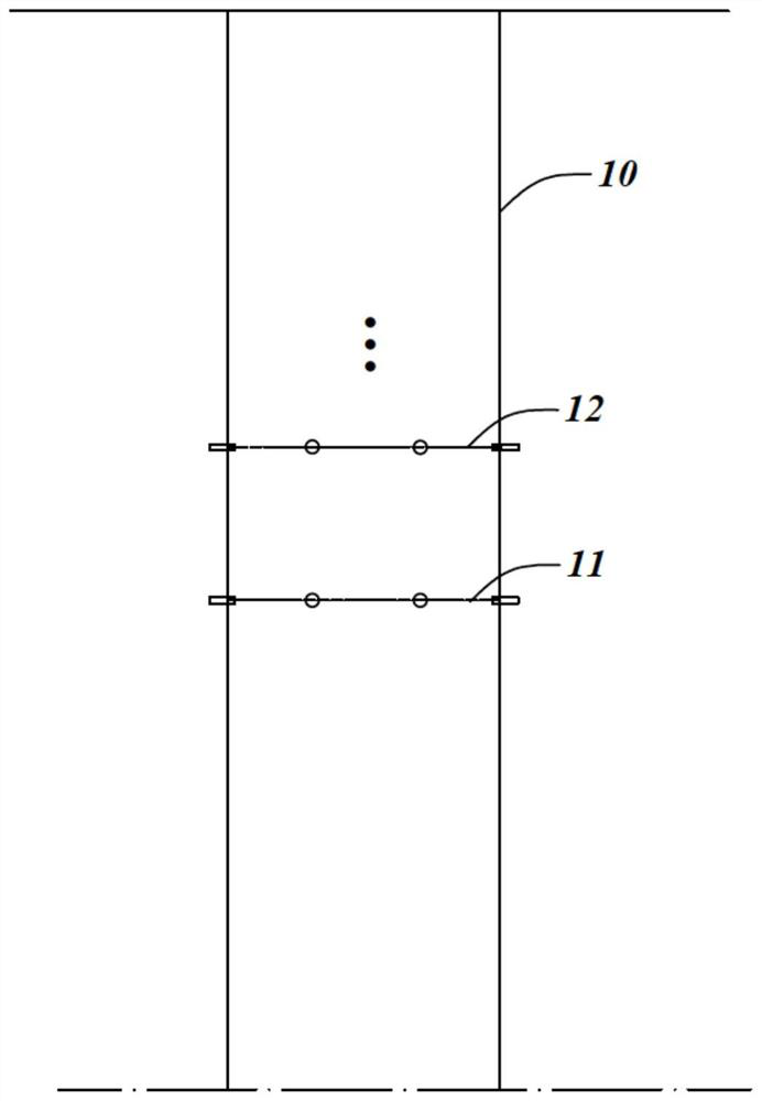
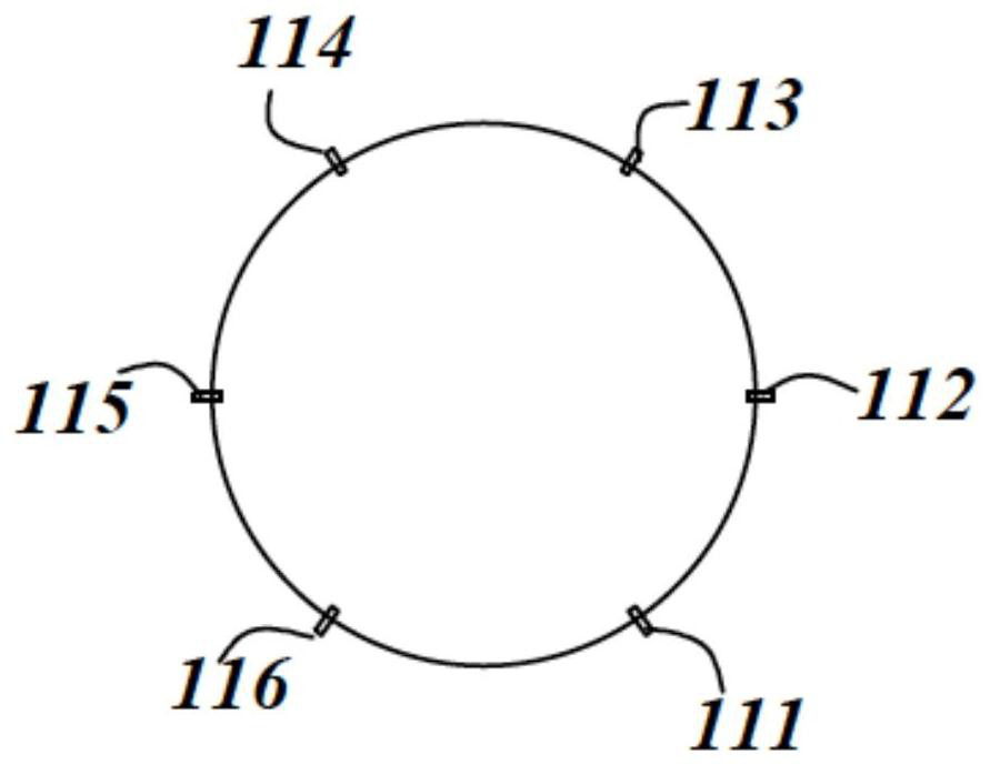
[0040] Example 1: Wellbore pressureless grouting method

[0041] ginseng Figure 2a , 2b As shown, the wall of the wellbore 10 includes a first section 11, a second section 12 . . . in order from bottom to top at different levels, and several grouting holes are equally spaced on each section, as shown in the present embodiment. 2m, the first section 11 is provided with grouting holes 111, 112, 113, 114, 115 and 116 in sequence, the cross section of the first section 11 is circular, and the 6 grouting holes are evenly distributed along the circumference at equal intervals. The spacing of the grouting holes is 2m, and the setting of the grouting holes on the other sections is the same as that of the first section, and will not be repeated here. In addition, a gate valve is correspondingly installed on each grouting hole to control the opening or closing of the grouting hole.

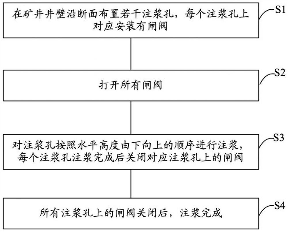
[0042] The specific steps of the pressureless grouting method in this embodiment are as follows:

...

Embodiment 2

[0049] Example 2: Roadway pressureless grouting method

[0050] ginseng Figure 3a , 3b As shown, the shaft wall of the roadway 20 includes a first section 21, a second section 22... A section 21 is provided with grouting holes 211, 212, 213, 214, 215 and 116 in sequence, the grouting holes 211 and 216 are located at the same level, the grouting holes 212 and 215 are located at the same level, Located at the same level, the spacing of the six grouting holes on the first section 11 is 2m, and the setting of the grouting holes on the other sections is the same as that of the first section, which will not be repeated here. In addition, a gate valve is correspondingly installed on each grouting hole to control the opening or closing of the grouting hole.

[0051] When grouting the roadway, it is necessary to install all the orifice pipes of the grouting section first, and then seal the grouting by shotcrete or masonry.

[0052] The specific steps of the pressureless grouting m...


PUM


Abstract

The invention discloses a non-pressure grouting method based on mine construction. The method comprises the following steps of, S1, arranging a plurality of grouting holes along the cross section of amine well wall, and correspondingly mounting a gate valve on each grouting hole; S2, opening all gate valves; S3, grouting the grouting holes according to the horizontal height from bottom to top, and closing the gate valves on the corresponding grouting holes after grouting of each grouting hole is completed; and S4, after all the gate valves on the grouting holes are closed, completing the grouting. According to the method, in the grouting process, the corresponding gate valves on the grouting holes subjected to the grouting are all opened, pressure relief can be effectively carried out, and grouting in the non-pressure state can be realized in the whole grouting process, so that the pressure of the well wall is greatly reduced, and the quality of the well wall is ensured.

Description

technical field [0001] The invention belongs to the technical field of mine construction and particularly relates to a pressureless grouting method based on mine construction. Background technique [0002] In mine construction (shafts and roadways), it is often encountered that the surrounding rock is relatively broken or there is a small amount of water gushing. Although it is safe to pass through bad rock formations, the surrounding rock after the shaft wall needs to be reinforced and the quality of the shaft wall is not very good due to water gushing. If it is good, it needs grouting reinforcement, and after passing through the bad rock formation, it will be reinforced behind the wall and water blocked. Due to the limited bearing pressure of the wellbore, how to ensure the quality of the wellbore during the grouting process is an urgent problem to be solved. [0003] Therefore, in view of the above technical problems, it is necessary to provide a pressureless grouting me...

Claims


Application Information

Patent Timeline
Patent Type & Authority Patents(China)
IPC IPC(8): E21D5/04E21D11/10
CPCE21D5/04E21D11/10
Inventor 张家乐王启龙汤冲冲秦振新张佳伟朱东阁李金斗张伟国
Owner CHINA COAL NO 3 CONSTR GRP
Why Eureka
Try Eureka