Stacked plate heat exchanger

A technology of heat exchangers and stacked plates, applied in the direction of heat exchange equipment, indirect heat exchangers, heat exchanger types, etc., can solve problems such as extra cost, reduce process reliability, leakage, etc., and achieve the goal of preventing process unreliability Effect

Active Publication Date: 2022-01-18
MAHLE INT GMBH
View PDF8 Cites 0 Cited by
  • Summary
  • Abstract
  • Description
  • Claims
  • Application Information

AI Technical Summary

Problems solved by technology

However, this dip tube is an additional component, which leads to additional costs and reduces process reliability due to possible leaks at the sealing points and connections between the dip tube and other components such as the cover or base plate

Method used


Image

  • Stacked plate heat exchanger
  • Stacked plate heat exchanger
  • Stacked plate heat exchanger

Examples


Embodiment Construction

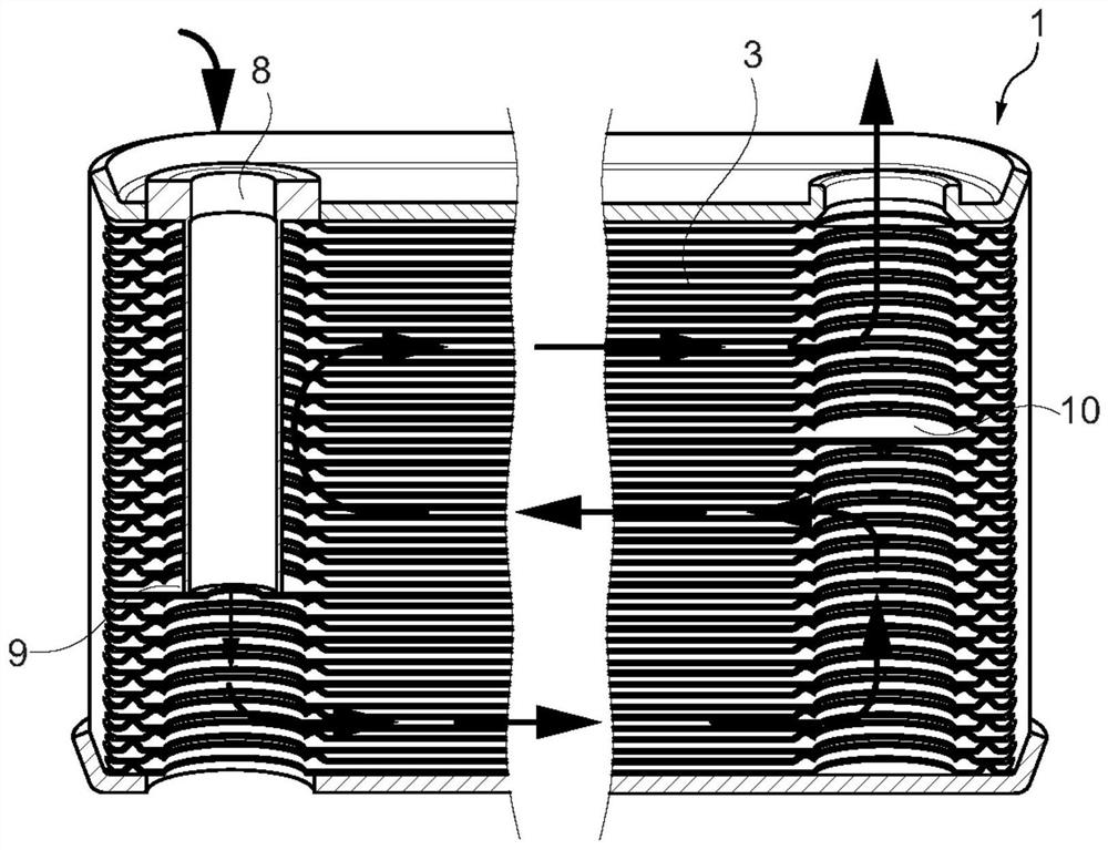
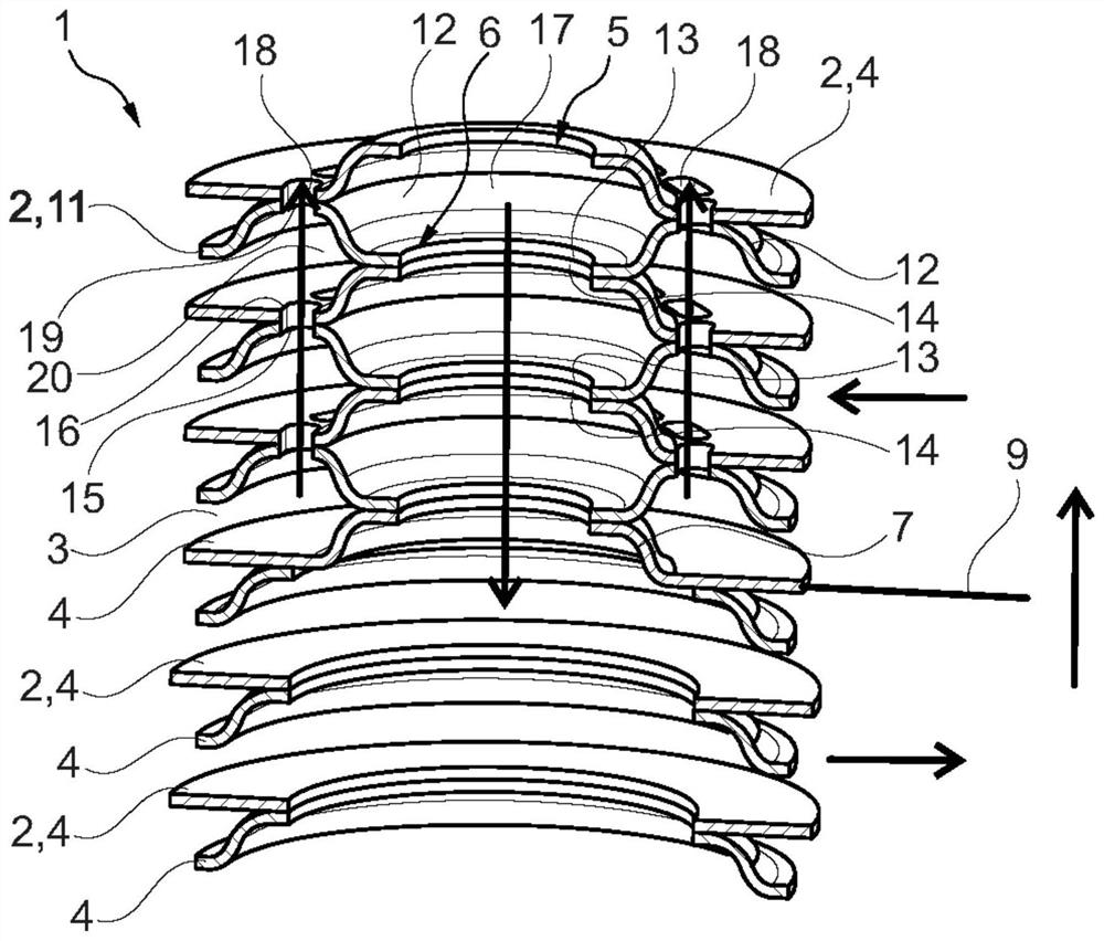
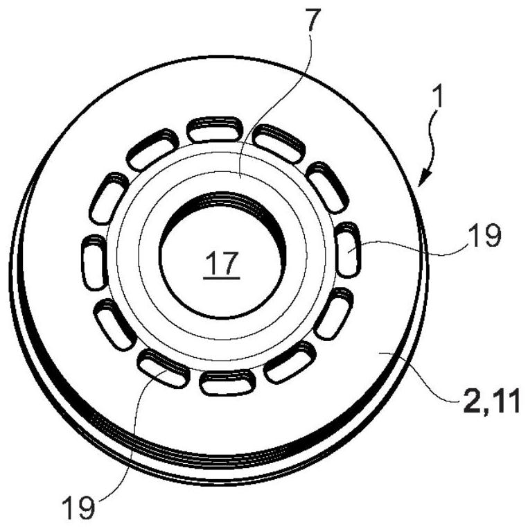
[0027] according to figure 1 , the stacked plate heat exchanger 1 comprises a plurality of stacked plates 2 stacked on top of each other and welded to each other, here are first stacked plates 4 between which are alternately formed Hollow spaces in different media3. At least one first passage opening 5 and at least one second passage opening 6 are provided in the first stack plate 4, wherein a dome 7 protruding from the stack plate plane surrounds the at least one first passage opening (see also Figure 2 to Figure 11 ). The stacked plate heat exchanger 1 additionally comprises an immersion tube 8 formed as a separate part which has to be tightly assembled in the stacked plate heat exchanger 1 and creates a predetermined flow path through the stacked heat exchanger 1 . This dip tube 8 formed as a separate part involves relatively high costs and also has a relatively high assembly outlay, so the stacked plate heat exchanger 1 according to the invention (eg Figure 2 to Figur...


PUM


Abstract

The invention relates to a stacked plate heat exchanger (1), comprising a plurality of stacked plates (2, 4), which are stacked on top of each other and welded to each other, wherein in the first stacked plate (4) is provided with at least one first passage opening (5) and at least one second passage opening (6), wherein a dome (7) protruding from the stack plate plane surrounds the at least one first passage opening (5) . It is important for the invention that at least one second stack plate (11) is provided, which likewise has at least one first passage opening (5) and second passage opening (6) with a protruding dome (7), wherein An annular flange (12) protruding from the plane of the stack of plates surrounds said second channel opening (6); the first stack of plates (4) and the second stack of plates (11) form a immersion tube channel (17).

Description

technical field [0001] The invention relates to a stacked plate heat exchanger according to the preamble of claim 1, comprising a plurality of stacked plates stacked on top of each other and welded to each other, between which stacked plates for two media are alternately formed hollow space. Background technique [0002] Stacked plate heat exchangers are known from the prior art, which are used, for example, as oil coolers, iConds or cooling devices in motor vehicles. A stacked plate heat exchanger comprises a plurality of longitudinally stacked plates stacked on top of each other with hollow spaces formed therebetween. The two media (cooling medium and medium to be cooled) flow in hollow spaces arranged one above the other so that heat exchange can take place between the two media. Here, the hollow space is delimited by the surface and the surface edge of the respective stack plate and the adjacently supported stack plate. In each stacking plate, generally four openings ...

Claims


Application Information

Patent Timeline
Patent Type & Authority Patents(China)
IPC IPC(8): F28D9/00F28F3/10F28F3/08
CPCF28D9/00F28F3/10F28F3/08F28D9/0043F28D9/005F28F9/026F28F3/12F28F3/048
Inventor A·多尔德尔A·德兰科夫T·费尔德克勒T·马杰T·默滕M·韦斯纳
Owner MAHLE INT GMBH
Why Eureka
Try Eureka