Display panel and display device
A technology for display panels and color filter substrates, applied in nonlinear optics, instruments, optics, etc., can solve the problems of high production cost, complex structure, and high production difficulty, so as to reduce the production difficulty and cost, improve the display color gamut, The effect of improving transmittance and backlight utilization
- Summary
- Abstract
- Description
- Claims
- Application Information
AI Technical Summary
Problems solved by technology
Method used
Image

Examples
Embodiment 1
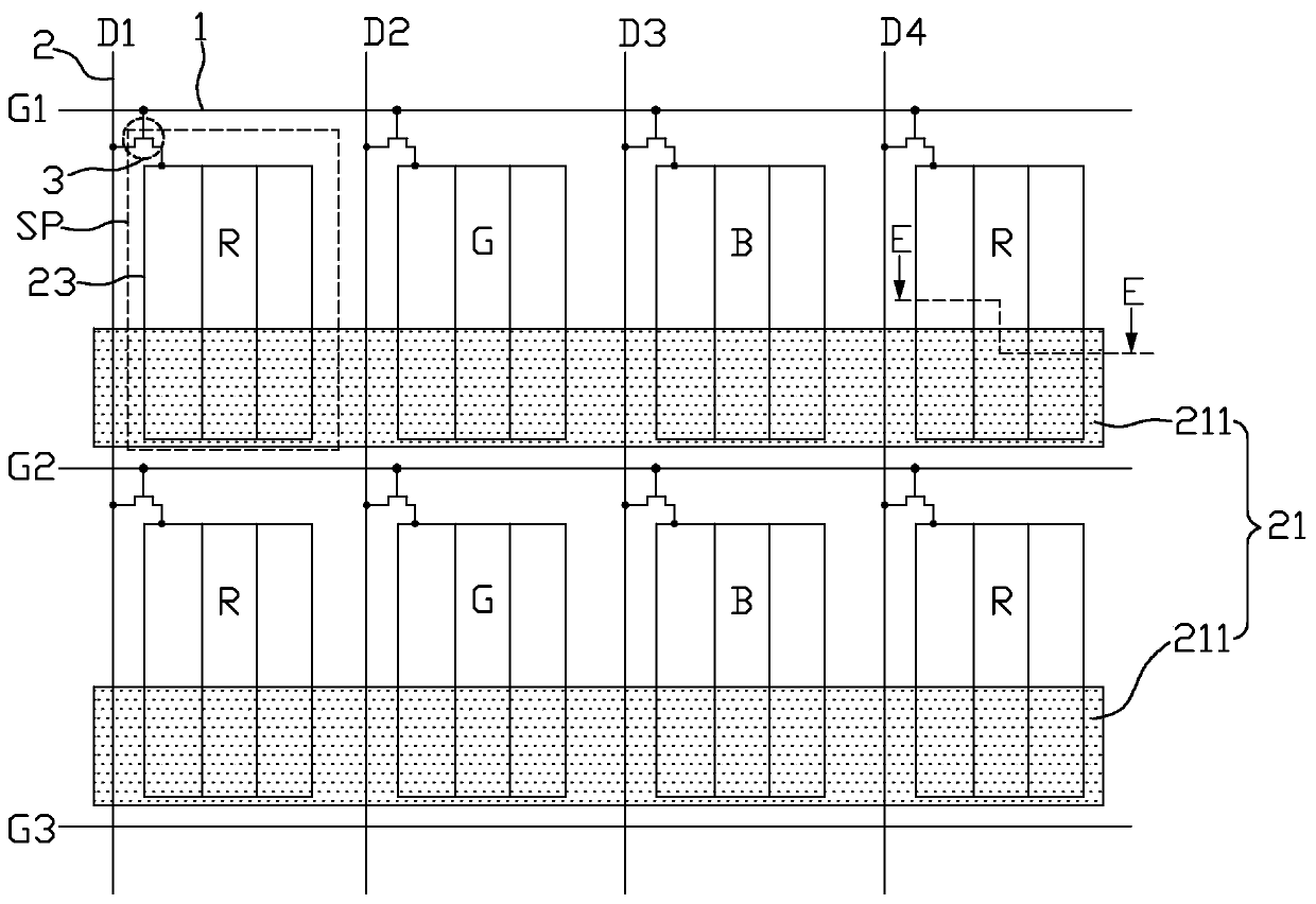
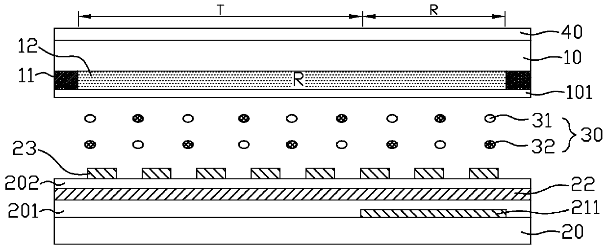
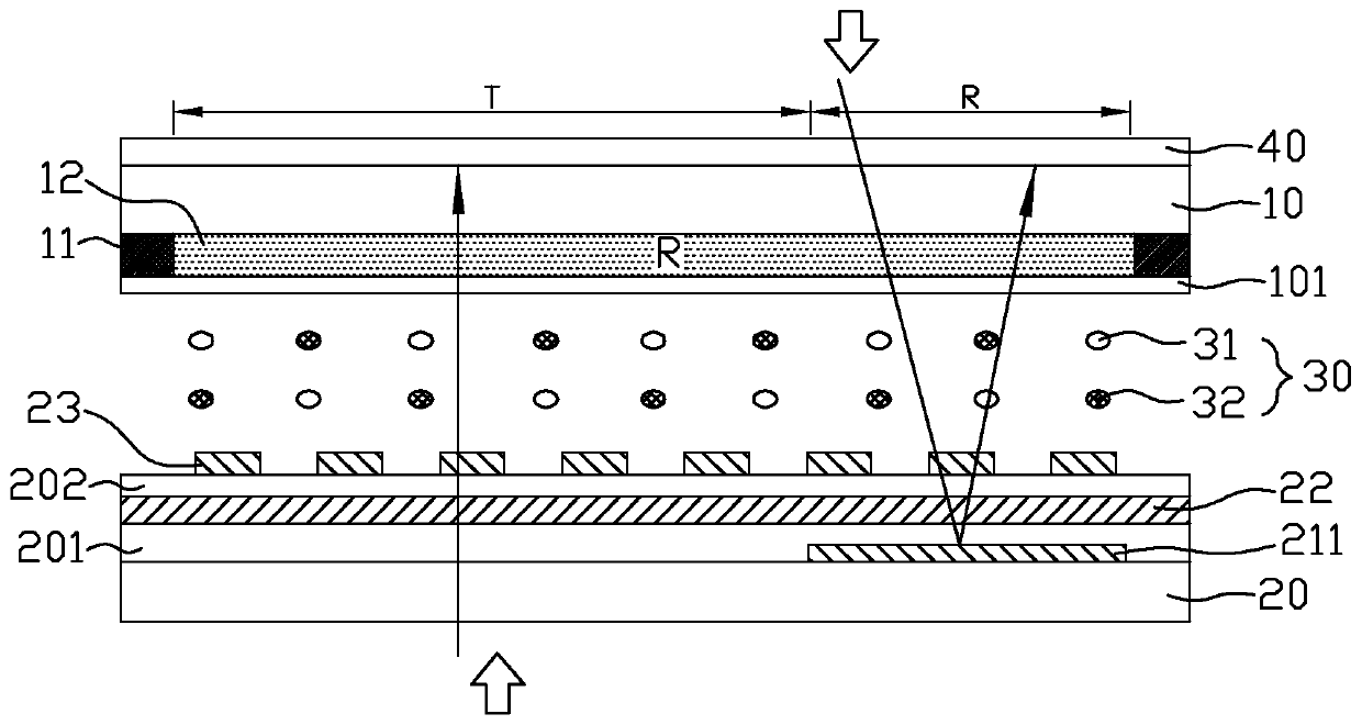
[0038] figure 1 is a schematic plan view of the display panel in Embodiment 1 or 2 of the present invention, figure 2 It is the display panel in the first embodiment of the present invention in the initial state along the figure 1 Schematic diagram of the cross-sectional structure at E-E in the middle, image 3 It is a schematic diagram of the light of the display panel in the dark state in Embodiment 1 of the present invention, Figure 4 yes image 3 Schematic diagram of the principle of the display panel in the dark state, Figure 5 It is a schematic diagram of the light of the display panel in the reflective and transmissive states in Embodiment 1 of the present invention, Figure 6 yes Figure 5 Schematic diagram of the principle of the display panel in reflective and transmissive states.
[0039] Such as Figure 1 to Figure 6 As shown, a display panel provided by Embodiment 1 of the present invention includes a color filter substrate 10 and an array substrate 20 d...
Embodiment 2
[0058] figure 1 is a schematic plan view of the display panel in Embodiment 1 or 2 of the present invention, Figure 7 It is the display panel in the second embodiment of the present invention in the initial state along the figure 1 Schematic diagram of the cross-sectional structure at E-E in the middle, Figure 8It is a schematic diagram of light rays of the display panel in the initial state in Embodiment 2 of the present invention, Figure 9 yes Figure 8 The principle schematic diagram of the display panel in the initial state, Figure 10 It is a schematic diagram of the light rays of the display panel in the reflection and transmission states in the second embodiment of the present invention, Figure 11 yes Figure 10 Schematic diagram of the principle of the display panel in reflective and transmissive states. Such as figure 1 , Figure 7 to Figure 11 As shown, the display panel provided by Embodiment 2 of the present invention is the same as Embodiment 1 ( Fig...
Embodiment 3
[0063] Figure 12 is a schematic plan view of the display panel in Embodiment 3 or 4 of the present invention, Figure 13 It is the display panel in the third embodiment of the present invention in the initial state along the Figure 12 Schematic diagram of the cross-sectional structure at F-F in the middle, Figure 14 It is a schematic diagram of the light of the display panel in the reflective state in the third embodiment of the present invention, Figure 15 It is a schematic diagram of the light rays of the display panel in the transmission state in the third embodiment of the present invention. Such as Figure 12 to Figure 15 As shown, the display panel provided by Embodiment 3 of the present invention is the same as Embodiment 1 ( Figure 1 to Figure 6 ) are basically the same, the difference is that in this embodiment, the display panel has multiple columns of blank areas, and no pixel electrodes 23 are arranged in the multiple columns of blank areas, that is, the a...
PUM
 Abstract
Description
Claims
Application Information
 - R&D Engineer
- R&D Manager
- IP Professional
- Industry Leading Data Capabilities
- Powerful AI technology
- Patent DNA Extraction
Browse by: Latest US Patents, China's latest patents, Technical Efficacy Thesaurus, Application Domain, Technology Topic.
© 2024 PatSnap. All rights reserved.Legal|Privacy policy|Modern Slavery Act Transparency Statement|Sitemap