
Nib of infrared touch pen

A technology of infrared touch and pen head, which is applied in the input/output process of data processing, instruments, electrical digital data processing, etc., and can solve the problem of large wear of the pen head

Pending Publication Date: 2019-11-05
BEIJING ASU TECH CO LTD
View PDF3 Cites 0 Cited by
  • Summary
  • Abstract
  • Description
  • Claims
  • Application Information

AI Technical Summary

Problems solved by technology

[0003] In the existing infrared stylus, the tip of the pen is made of translucent resin around the infrared light emitting diode (Light Emitting Diode, LED), which will cause greater wear and tear of the tip when used.

Method used


Image

  • Nib of infrared touch pen
  • Nib of infrared touch pen

Examples


Embodiment Construction

[0017] The following will clearly and completely describe the technical solutions in the embodiments of the present invention with reference to the accompanying drawings in the embodiments of the present invention. Obviously, the described embodiments are only some, not all, embodiments of the present invention. Based on the embodiments of the present invention, all other embodiments obtained by persons of ordinary skill in the art without making creative efforts belong to the protection scope of the present invention.

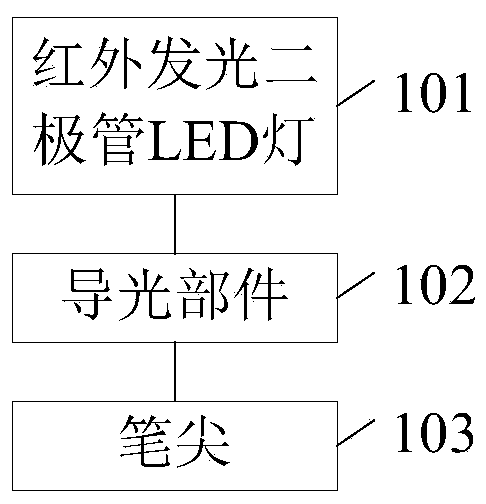
[0018] In the existing infrared stylus, the nib is made of translucent resin on the periphery of the infrared LED. The nib is formed of translucent resin. The nib is generally relatively thick, which causes the nib to be more worn during use.

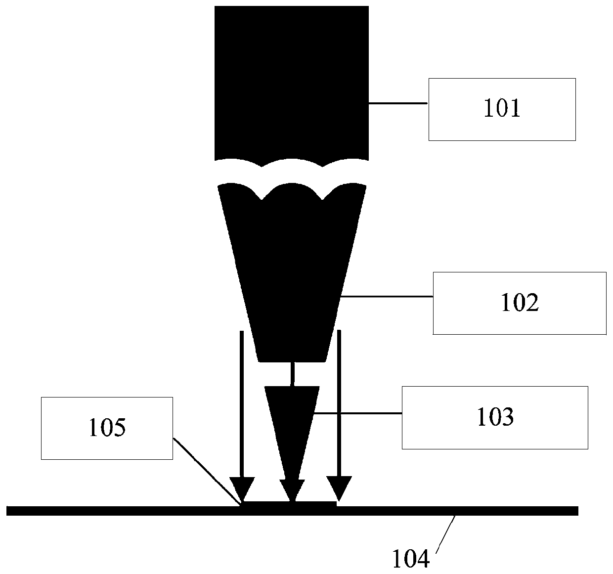
[0019] In order to reduce the abrasion of the tip of the infrared stylus during use on the basis of realizing the light guide requirement of the infrared stylus, an embodiment of the present invention provides a tip of t...


PUM


Abstract

The embodiment of the invention provides a pen point of an infrared touch pen. The pen point of the infrared touch pen comprises an infrared LED lamp, a light guide part and a pen point. The pen pointis made of a material of which the hardness meets a preset condition; the infrared LED lamp is used for generating infrared light when the pen point is close to or in contact with the touch surface.The light guide part is used for projecting infrared light to the touch surface so as to form light spots on the touch surface. The abrasion during use can be reduced.

Description

technical field [0001] The invention relates to the field of infrared touch technology, in particular to a tip of an infrared touch pen. Background technique [0002] For the projected content on the desktop or wall, if you want to use a pen product, such as an infrared stylus, to directly perform touch operations such as clicking, sliding, and dragging on the projected content, you need to cooperate with an infrared camera, an infrared stylus and Infrared algorithms are used together. Specifically, the infrared stylus is the same as generating an infrared signal. The infrared signal captured by the infrared camera and projected by the infrared stylus determines the touch data generated by the infrared stylus against the desktop or wall, and the touch data is used to target the projected content. to operate. [0003] In the existing infrared stylus, the tip of the pen is composed of translucent resin around the infrared light emitting diode (Light Emitting Diode, LED), whi...

Claims


Application Information

Patent Timeline
Patent Type & Authority Applications(China)
IPC IPC(8): G06F3/0354
CPCG06F3/03542
Inventor 阿布都
Owner BEIJING ASU TECH CO LTD
Learn More