
Back light system

A technology of backlight system and light source, which is applied in the field of backlight system, can solve the problems of high cost, single function, cumbersome color filter manufacturing process, etc., and achieve the effect of low cost and easy assembly

Inactive Publication Date: 2004-07-14
HONG FU JIN PRECISION IND (SHENZHEN) CO LTD +1
View PDF0 Cites 2 Cited by
  • Summary
  • Abstract
  • Description
  • Claims
  • Application Information

AI Technical Summary

Problems solved by technology

[0006] In order to overcome the technical problems of cumbersome manufacturing process, high cost, large number of backlight system components, single function and high cost in the prior art, the present invention provides a backlight system with light filtering function

Method used


Image

  • Back light system
  • Back light system
  • Back light system

Examples


Embodiment Construction

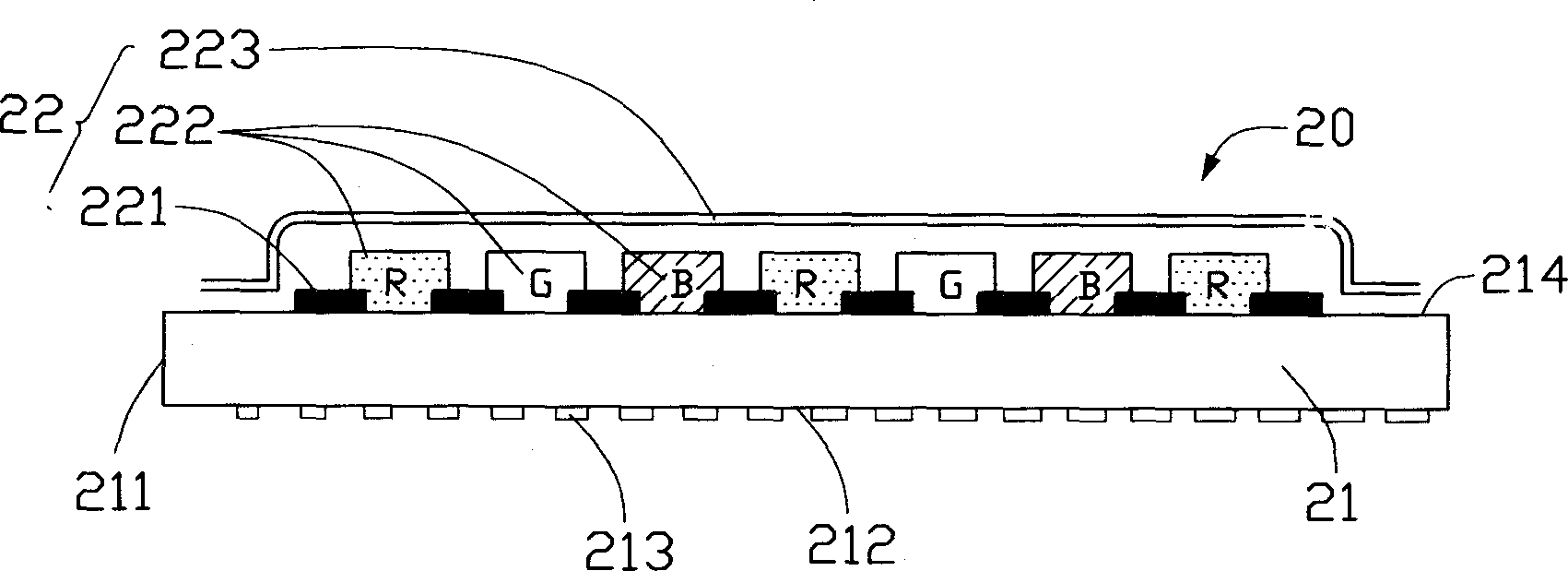
[0015] Please refer to image 3 As shown, the light guide plate 20 used in the backlight system of the present invention is made of transparent materials such as acrylic, glass or polycarbonate. The light guide plate 20 includes a light guide base 21 and a filter unit 22, wherein the light guide The substrate 21 is in the shape of a flat plate, which has a light incident surface 211, a bottom surface 212 connected to the light incident surface 211, and a light exit surface 214 opposite to the bottom surface 212, wherein the bottom surface 212 has a plurality of scattering units, and the scattering units are convex Point 213 , the size of the bumps 213 increases along the direction away from the light incident surface 211 and the arrangement gradually changes from sparse to dense. In addition, the light guide base 21 can also be designed as a wedge or a triangle as required. The filter unit 22 is composed of a light-shielding layer 221 for light-shielding, red (R), green (G), ...


PUM

PropertyMeasurementUnit
thicknessaaaaaaaaaa
thicknessaaaaaaaaaa
optical densityaaaaaaaaaa

Abstract

The back light system includes one light guiding plate and at least one light source. The light guiding plate includes one light guiding substrate and one optical filter unit located on the substrate, the light guiding substrate has at least one light incident plane, one bottom plane with several scattering units and connected to the light incident plane and one light out-going plane opposite to the bottom plane; and the optical filter unit includes shading layer distributed intermittently in the light out-going plane of the light guiding substrate, colorizing layer in the opening part of the shading layer and protecting layer on the surface of the shading layer and colorizing layer. The back light system of the present invention has not only light guiding function and light filtering function.

Description

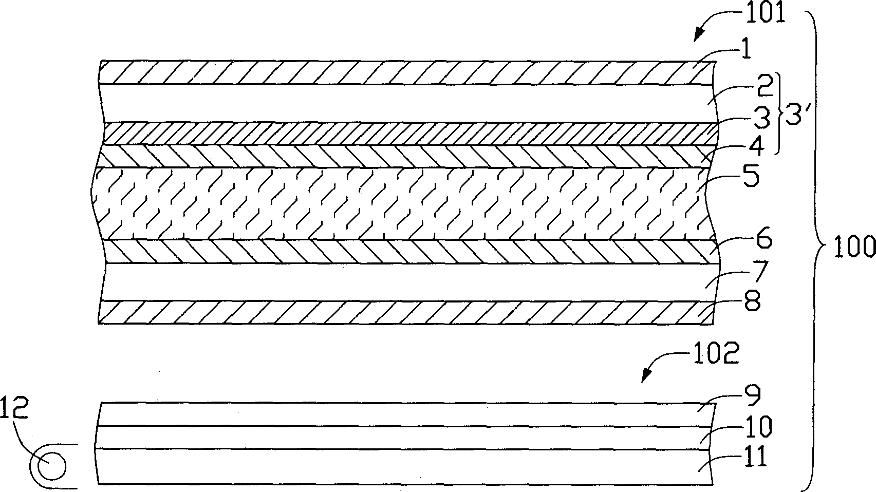
【Technical field】 [0001] The invention relates to a backlight system. 【Background technique】 [0002] Since the advent of liquid crystal display, it has been attracting more and more attention from consumers and businesses with its advantages of thinness, power saving, no radiation, and full-color display, and its application fields have become wider and wider. see figure 1 A prior art liquid crystal display 100 includes a liquid crystal panel 101 and a backlight system 102, wherein the liquid crystal panel 101 includes upper and lower substrates 2, 7 and a liquid crystal layer 5 sealed between the two substrates 2, 7, formed on the upper substrate The ITO (Indium Tin Oxide, indium tin oxide) transparent electrode layer 4 of 2 and the TFT (Thin Film Transistor, thin film transistor) structure 6 formed on the lower substrate 7 are provided on the outside of the two substrates 2 and 7 for controlling the on-off of light. The first and second polarizers 1, 8, and the color fi...

Claims


Application Information

Patent Timeline
Patent Type & Authority Applications(China)
IPC IPC(8): G02F1/1335G02F1/13357
Inventor 陈杰良吕昌岳
Owner HONG FU JIN PRECISION IND (SHENZHEN) CO LTD
Learn More