Bending pliers former and forming method thereof

A former and plier head technology, applied in the bending plier head former and its forming field, can solve the problems of enlarged wound, inconvenient operation, laborious pressing and bending process, etc., and achieve the advantages of enhanced stability, improved operation efficiency and reasonable structural design. Effect

Active Publication Date: 2020-08-14
杭州煜昊科技有限公司
View PDF9 Cites 0 Cited by
  • Summary
  • Abstract
  • Description
  • Claims
  • Application Information

AI Technical Summary

Problems solved by technology

[0002] A variety of tools are needed to perform surgery, and clamps are one of the important tools for grasping. The existing clamp heads are generally straight. , when treating the side or depth of the wound, it is easy to cause the wound to expand, and bending the pliers head can avoid this situation, but there is no bending tool for the pliers head on the market
For example, the publication date is 20161221, and the Chinese patent with the publication number CN205817276U discloses a special tooling for the bending, welding and inspection of the cover plate tube of the auger oil dipstick. This utility model is not accurate enough for the bending position and angle of the workpiece. , and the bending process is laborious or requires the use of other tools for bending, which is inconvenient to operate

Method used


Image

  • Bending pliers former and forming method thereof
  • Bending pliers former and forming method thereof
  • Bending pliers former and forming method thereof

Examples


Embodiment Construction

[0036] The present invention will be further described in detail below in conjunction with the accompanying drawings and examples. The following examples are explanations of the present invention and the present invention is not limited to the following examples.

[0037] Example.

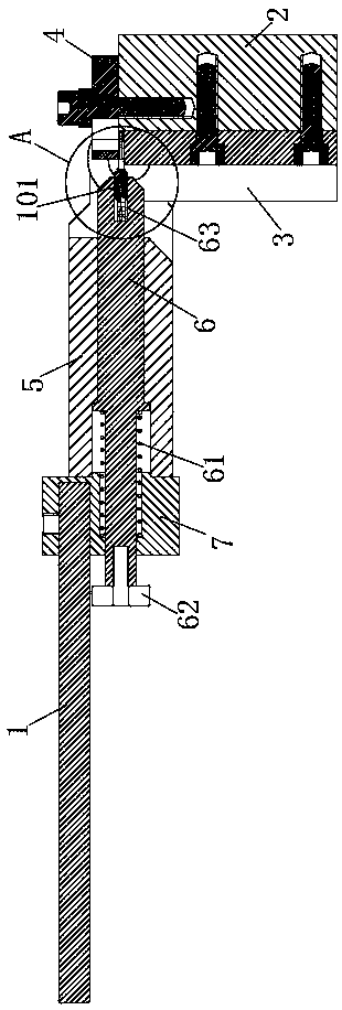
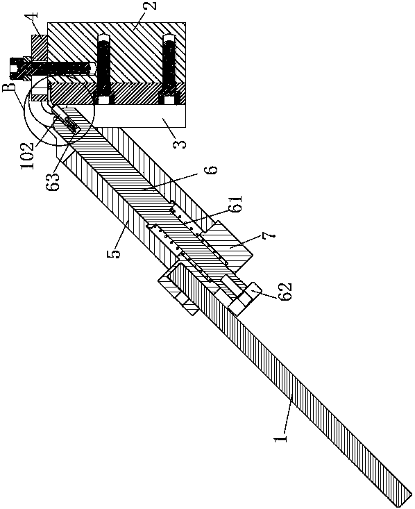
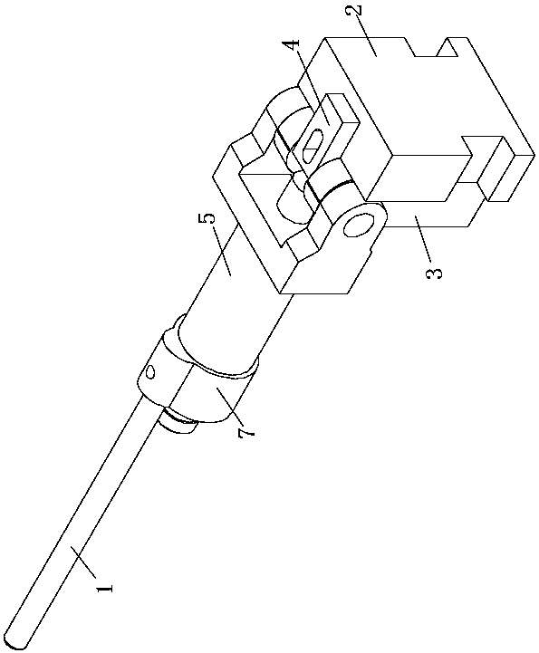
[0038] see Figure 1 to Figure 13 , the curved pliers shaper in the present embodiment includes a handle 1, a base 2, a positioning plate 3, a pressing plate 4, a bending part 5, a telescopic pressing rod 6 and a stuffy cover 7; Long holes 41; the pressing plate 4 is installed on the top of the base 2 by bolts; the base 2 is also provided with a screw hole 21 for connecting the pressing plate 4; the base 2 is also provided with a mounting groove 23 for connecting the workbench.

[0039] The positioning plate 3 in the present embodiment is fixed on the base 2; the top of the positioning plate 3 is provided with a pliers bending groove 31; The shape of the curved surface 32 ; the bending groove 31 ...


PUM


Abstract

The invention relates to a bending tong head former and a forming method thereof, and provides a technical scheme for solving the problem that there is no bending workpiece aiming at a tong head in the prior art, a bending tong head former comprises a handle, a base, a positioning plate, a pressing plate, a bending piece, a telescopic pressing rod and a blank cap; the positioning plate is fixed on the base; the top of the positioning plate is provided with a tong head bending groove; the pressing plate is arranged on the top of the base through a bolt; the bending piece is rotationally connected with the base; the lower edge of the end face of the bending piece facing the positioning plate is provided with an inclined plane for positioning; a cavity for installing the telescopic pressingrod is arranged in the bending piece; the telescopic pressing rod comprises a rod body, a spring and a limit nut; the rod body is connected with the inner wall of the cavity in a sliding way; one endof the rod body close to the positioning plate is provided with a tong head bending die cavity; and one end of the rod body far away from the positioning plate is connected with the limiting nut. Thebending tong head former has good forming effect on the tong head, and is practical, convenient and labor-saving.

Description

technical field [0001] The invention relates to a former and a forming method thereof, in particular to a bending pincer former and a forming method thereof. Background technique [0002] A variety of tools are needed to perform surgery, and clamps are one of the important tools to achieve the gripping effect. The existing clamp heads are generally straight. , When treating the side or depth of the wound, it is easy to cause the wound to expand, and bending the pliers head can avoid this situation, but there is no bending tool for the pliers head on the market at present. For example, the publication date is 20161221, and the Chinese patent with the publication number CN205817276U discloses a special tooling for the bending, welding and inspection of the cover plate tube of the auger oil dipstick. This utility model is not accurate enough for the bending position and angle of the workpiece. , and the bending process is laborious or requires the use of other tools for bendin...

Claims


Application Information

Patent Timeline
Patent Type & Authority Patents(China)
IPC IPC(8): B21D7/06B21D7/16B21D43/00
CPCB21D7/063B21D7/16B21D43/003
Inventor 吴毅忠叶林李向松王孟翔鲍善斌
Owner 杭州煜昊科技有限公司
Why Eureka
Try Eureka