Automatic bending machine for continuously bending FPC board

A bending machine, automatic technology, applied in the direction of electrical components, printed circuit manufacturing, printed circuit, etc., can solve the problems that affect the product position accuracy and dimensional accuracy, increase the loss of parts and maintenance costs, reduce work efficiency, etc., to improve The effect of bending position accuracy, improving product yield, and improving work efficiency

Pending Publication Date: 2022-02-15
苏州市锐翊电子科技有限公司
View PDF0 Cites 0 Cited by
  • Summary
  • Abstract
  • Description
  • Claims
  • Application Information

AI Technical Summary

Problems solved by technology

[0003] According to the requirements of use, it is necessary to bend the FPC board at different positions. However, the bending machine currently used has the following disadvantages: during the bending process of the FPC board, the head and tail of the FPC board are under the bending force. After that, it will move to the bending place for a certain displacement, which leads to the need to reposition the position of the FPC board when the next bending is performed, which not only makes the whole bending work unable to be carried out continuously, but also greatly reduces the work efficiency. It is easy to have the phenomenon of bending position deviation, which will cause product scrapping and affect the yield of the product
In addition, in order to ensure that the bending shape of the FPC board can meet the requirements, the extrusion force between the upper mold structure and the lower mold structure of the bending structure is relatively large, and the extrusion time is longer. After a long period of bending work, the lower mold Under the pressure of the upper die structure, the structure is prone to displacement or even deformation, which not only affects the positional accuracy and dimensional accuracy of the product obtained by bending, but also increases the loss of parts and maintenance costs

Method used


Image

  • Automatic bending machine for continuously bending FPC board
  • Automatic bending machine for continuously bending FPC board
  • Automatic bending machine for continuously bending FPC board

Examples


Embodiment 1

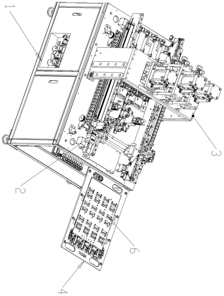
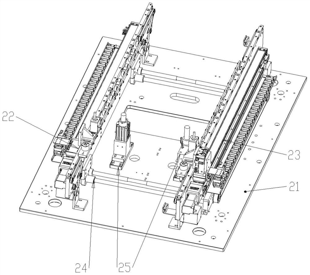
[0035] Such as figure 1 Shown is a perspective view of the present invention, including a frame 1, a transmission structure 2, a bending structure 3, and a carrier structure 4, the transmission structure 2 is arranged on the frame 1, and the bending structure 3 is arranged on the frame 1 In the upper middle position, the carrier structure 4 moves along the conveying structure 2, and performs bending work at the position of the bending structure 3; wherein, as figure 2 Shown is a perspective view of the transmission structure 2, including a fixed base plate 21, a first side transmission structure 22, a second side transmission structure 23, a width adjustment structure 24, and a carrier positioning structure 25. The first side transmission structure 22. The second side transmission structure 23 is relatively arranged on both sides of the fixed substrate 21, and the width adjustment structure 24 is arranged on the fixed substrate 21 and respectively connected to both ends of th...


PUM


Abstract

The invention discloses an automatic bending machine for continuously bending an FPC board and a working method thereof. The automatic bending machine comprises a rack, a conveying structure, a bending structure and a carrier structure; the conveying structure comprises a fixed base plate, a first side conveying structure, a second side conveying structure, a width adjusting structure and a carrier positioning structure. The bending structure comprises an upper die structure assembly and a lower die structure assembly; and the carrier structure comprises a placing plate, a pressing plate, a limiting pin, an end part positioning structure and a shifting roller structure. According to the invention, the multiple sets of FPC boards needing to be bent are sequentially placed on the carrier structure and reach the bending structure to be bent under the conveying effect of the conveying structure, after each time of bending, the positions of the FPC boards on the carrier structure are repositioned through the material shifting roller structure, and therefore the working efficiency and the bending quality of the bending machine are greatly improved.

Description

technical field [0001] The invention relates to the field of FPC board production, in particular to an automatic bending machine for continuous bending of FPC boards. Background technique [0002] FPC board is a highly reliable and excellent flexible printed circuit board made of polyimide or polyester film, because of its high wiring density, light weight, thin thickness, bending It is widely used in the electronic equipment industry due to its good foldability and other advantages. [0003] According to the requirements of use, it is necessary to bend the FPC board at different positions. However, the bending machine currently used has the following disadvantages: during the bending process of the FPC board, the head and tail of the FPC board are subjected to bending force. Afterwards, it will move a certain displacement to the bending place, which leads to the need to reposition the position of the FPC board when the next bending is performed, which not only makes the wh...

Claims


Application Information

Patent Timeline
Patent Type & Authority Applications(China)
IPC IPC(8): H05K3/00
CPCH05K3/00
Inventor 陈良柱
Owner 苏州市锐翊电子科技有限公司
Why Eureka
Try Eureka