Automatic production robot for power busway

A technology for automatic production and busway, applied in metal processing equipment, feeding device, positioning device, etc., can solve the complicated bending operation of busway side plate, inaccurate measurement of busway side plate, unstable manual bending, etc. Problems, to achieve high work efficiency, low labor intensity, and improve stability

Active Publication Date: 2018-11-06
江苏汇成电气有限公司
View PDF8 Cites 1 Cited by
  • Summary
  • Abstract
  • Description
  • Claims
  • Application Information

AI Technical Summary

Problems solved by technology

[0003] In order to solve the above problems, the present invention provides an automatic production robot for electric busway, which can solve the existing Z-shaped busway side plate processing process and manually measure the busway side plate according to the specifications of the busway. Manually use existing bending tools to bend the side panels of the bus duct. Manual measurement of the side panels of the bus duct is inaccurate, and the bending tools need to be adjusted manually for bus ducts of different specifications, and the side panels of the bus duct are manually bent. Complicated, unstable manual bending, high labor intensity and low work efficiency, etc., can realize the function of automatic processing and bending of the Z-shaped busway side plate, can perform accurate bending operations, and has simple operation and good stability , low labor intensity and high work efficiency

Method used


Image

  • Automatic production robot for power busway
  • Automatic production robot for power busway
  • Automatic production robot for power busway

Examples


Embodiment Construction

[0017] In order to make the technical means, creative features, goals and effects achieved by the present invention easy to understand, the present invention will be further described below in conjunction with specific illustrations.

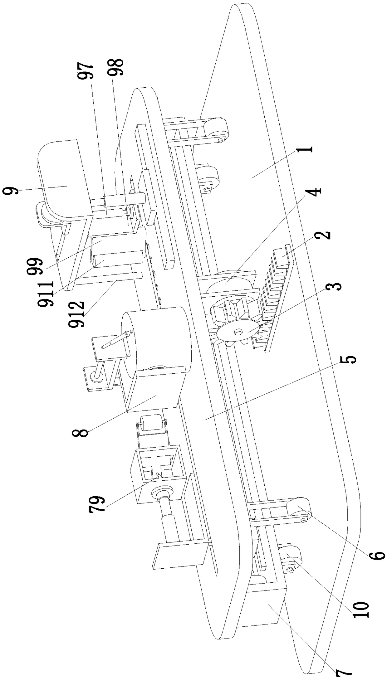
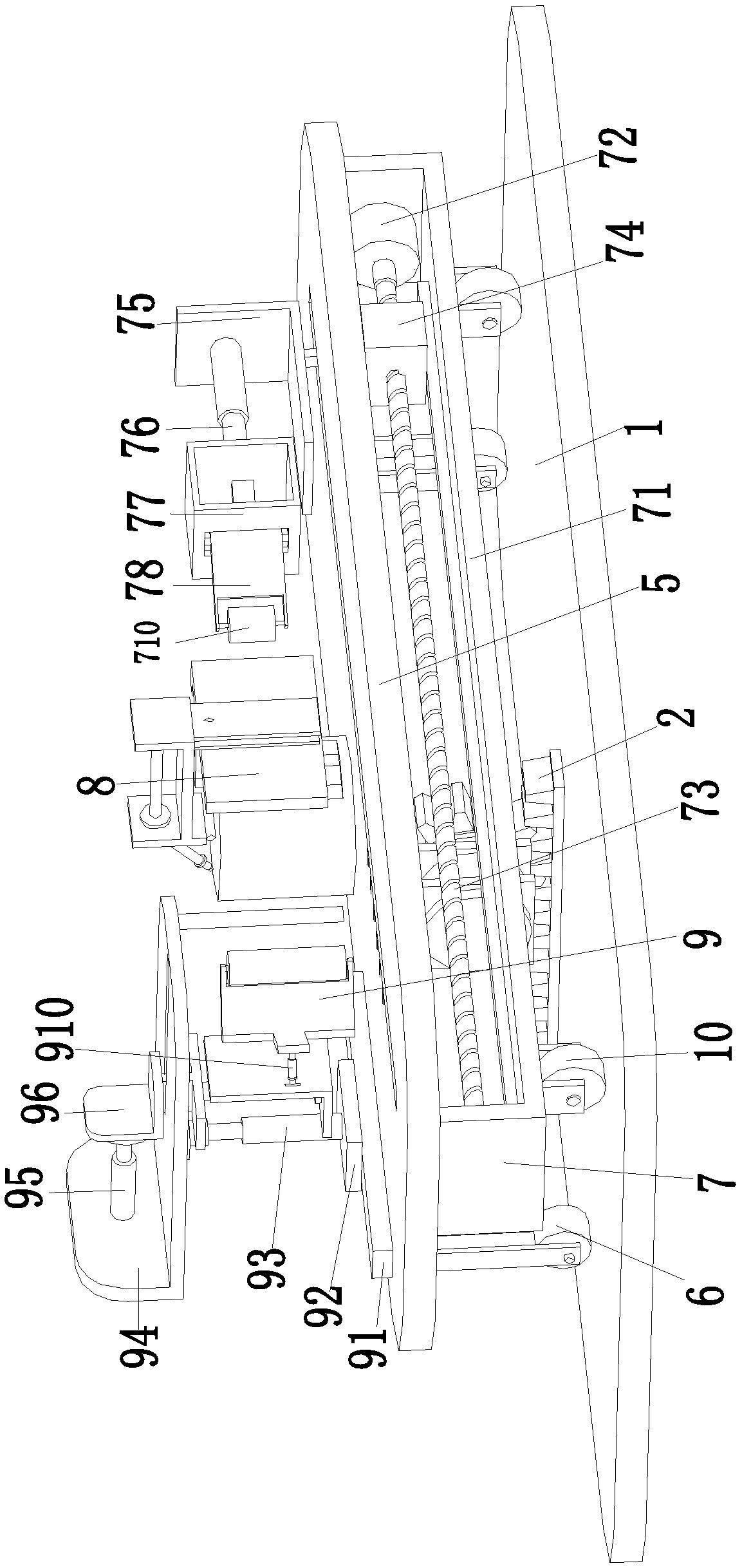
[0018] Such as Figure 1 to Figure 3As shown, a robot for automatic production of power bus ducts includes a bottom plate 1, on which a moving rack 2 is mounted, on which the moving rack 2 is meshed with a moving gear 3, and the moving gear 3 is installed on the output shaft of the moving motor 4, The mobile motor 4 is installed on the mounting plate 5 through the motor base, and the lower side of the front end of the mounting plate 5 is provided with two No. 1 auxiliary wheels 6, and the two No. 1 auxiliary wheels 6 are symmetrically located on the left and right sides of the mounting plate 5, and the mounting plate 5 The rear side of the body is provided with an adjusting moving groove, and an adjusting bending device 7 is arranged in the adju...


PUM


Abstract

The invention relates to an automatic production robot for a power busway. The automatic production robot comprises a bottom plate. A moving rack is mounted on the bottom plate and meshes with a moving gear. The moving gear is mounted on an output shaft of a moving motor. The moving motor is mounted on a mounting plate through a motor seat. An adjusting moving groove is formed in the rear side ofthe mounting plate and internally provided with an adjusting bending device. A blocking device is mounted on the front side of the upper end of the mounting plate. A feed bending device is arranged atthe left end of the mounting plate. According to the automatic production robot, the difficult problems that in the machining process of an existing Z-shaped busway side plate, the busway side plateneeds to be measured manually according to the specifications of busways, the busway side plate needs to be bent manually through a bending tool, manual measuring of the busway side plate is inaccurate, the bending tool needs to be adjusted manually as for the busways of different specifications, manual bending operation for the busway side plate is complex, manual bending is unstable, the labor intensity is high, and the work efficiency is low can be solved.

Description

technical field [0001] The invention relates to the field of electric equipment, in particular to an automatic production robot for electric bus ducts. Background technique [0002] The busway is a closed metal device composed of copper and aluminum busbar columns. The side plates are the left and right shell surfaces of the busway shell, usually referring to a component on the busway equipment, which is the shell component that makes up the busway. The slot generally consists of multiple structures such as the beginning bus duct, the straight bus duct, the L-shaped vertical bent bus, the Z-shaped vertical offset bus, and the T-shaped vertical. The side panels of the Z-shaped bus duct shell require manual labor during the production process According to the specifications of the bus duct, the side panel of the bus duct needs to be manually bent with the help of the existing bending tools. The manual measurement of the side panel of the bus duct is not accurate, and the bus d...

Claims


Application Information

Patent Timeline
Patent Type & Authority Applications(China)
IPC IPC(8): B21D5/04B21D43/00
Inventor 郑文豪
Owner 江苏汇成电气有限公司
Why Eureka
Try Eureka