Laser cutting machine

A laser cutting machine, laser technology, applied in laser welding equipment, welding equipment, metal processing equipment and other directions, can solve the problems of inconvenience and easy damage to the laser generator, and achieve the effect of convenient adjustment

Pending Publication Date: 2019-11-08
东莞烨东机电科技有限公司
View PDF8 Cites 0 Cited by
  • Summary
  • Abstract
  • Description
  • Claims
  • Application Information

AI Technical Summary

Problems solved by technology

[0002] At present, the light guide tube of the high-power laser cutting machine is fixed. When it is installed on the equipment, if it needs to be adjusted, the entire laser cutting machine needs to be moved, which is very inconvenient and easy to damage the laser generator.

Method used


Image

  • Laser cutting machine
  • Laser cutting machine
  • Laser cutting machine

Examples


Embodiment Construction

[0019] The following will clearly and completely describe the technical solutions in the embodiments of the present invention with reference to the accompanying drawings in the embodiments of the present invention. Obviously, the described embodiments are only some, not all, embodiments of the present invention. Based on the embodiments of the present invention, all other embodiments obtained by persons of ordinary skill in the art without making creative efforts belong to the protection scope of the present invention. It can be understood that the drawings are provided for reference and description only, and are not intended to limit the present invention. The connection relationship shown in the drawings is only for the convenience of clear description, and does not limit the connection mode.

[0020] It should be noted that when a component is considered to be "connected" to another component, it may be directly connected to the other component, or there may be intervening ...


PUM


Abstract

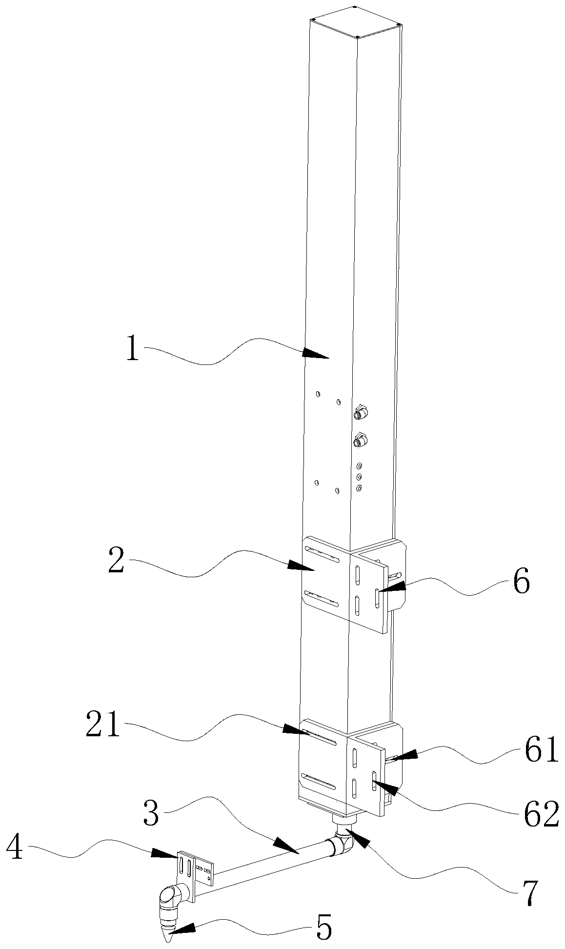
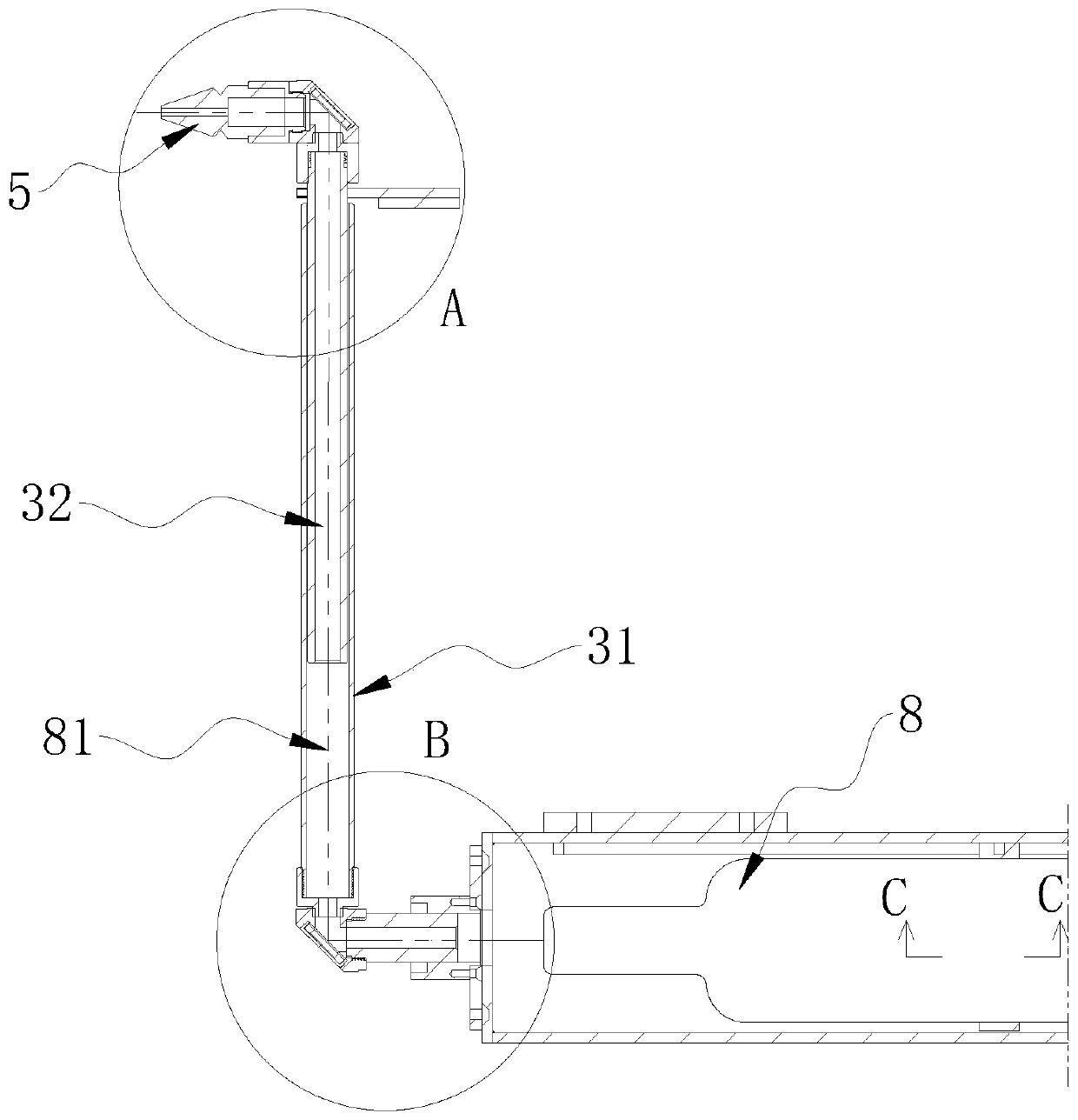
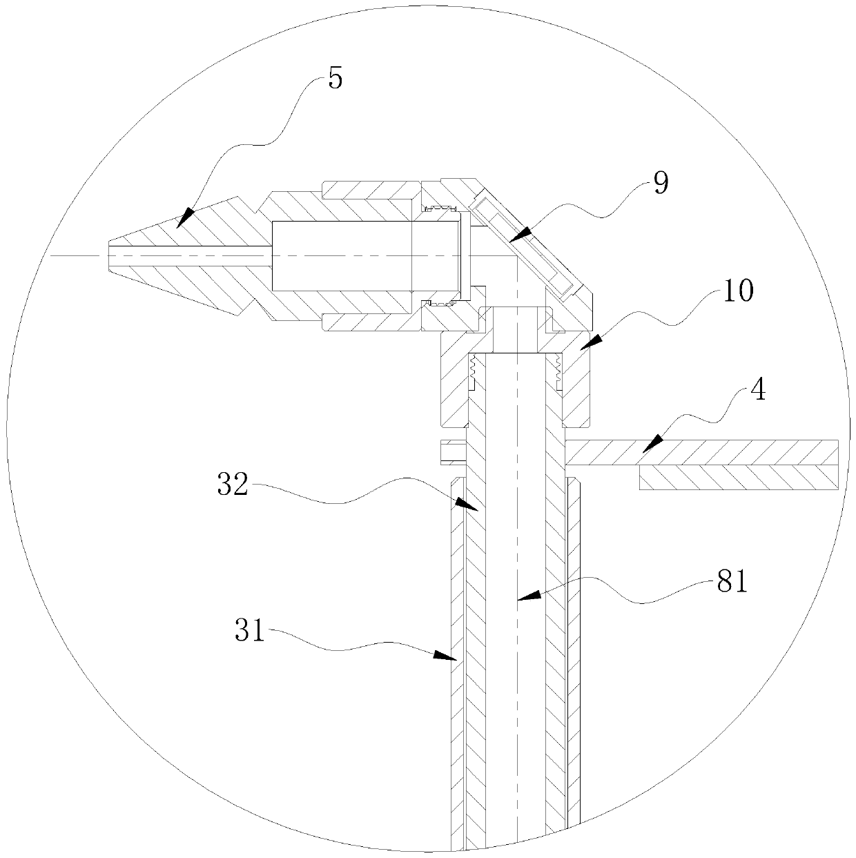
The invention discloses a conveniently adjusted laser cutting machine which comprises a shell, a laser generator fixed in the shell, a horizontally arranged light guide pipe arranged below an output end of the laser generator, two reflector seats separately fixed to two ends of the light guide pipe and a laser nozzle fixedly connected to the reflector seat arranged at the end, far away from the shell, of the light guide pipe. A reflector is fixed in each reflector seat. The reflective surfaces of the two reflectors are opposite to each other, and the included angles between the reflective surfaces and the horizontal plane are 45-degree angles. A connecting part is arranged between the light guide pipe and the laser generator. The connecting part is rotatably connected to the shell, and therotating axis of the connecting part and the laser ray emitted by the laser generator are overlapped. A vertical light guide through hole is formed in the connecting part, so that laser emitted by the laser generator can irradiate to the central axis of the light guide through hole of the reflective surface close to the shell to pass the reflective surface, close to the shell, of the reflector, and the central axis of the light guide through hole passes an output end of the laser generator.

Description

technical field [0001] The invention belongs to the technical field of laser cutting, and in particular relates to a laser cutting machine. Background technique [0002] At present, the light guide tube of the high-power laser cutting machine is fixed. When it is installed on the equipment, if it needs to be adjusted, the entire laser cutting machine needs to be moved, which is very inconvenient and easy to damage the laser generator. Contents of the invention [0003] In order to solve the technical problem in the prior art that the adjustment of the laser cutting machine needs to move the laser cutting machine as a whole, the purpose of the present invention is to provide a laser cutting machine. The present invention makes the light guide tube rotate 360 ​​degrees by setting a rotating connecting piece, thereby The adjustment of the laser cutting machine can be realized without moving the laser cutting machine as a whole. [0004] The technical scheme adopted in the pr...

Claims


Application Information

Patent Timeline
IPC IPC(8): B23K26/06B23K26/064B23K26/38B23K26/70
CPCB23K26/0643B23K26/38B23K26/064B23K26/702
Inventor 陈永坪
Owner 东莞烨东机电科技有限公司
Why Eureka
Try Eureka