Automatic discharging device

A technology of automatic cutting and material section, applied in the direction of transportation and packaging, conveyor objects, roller tables, etc., can solve the problems of labor and time consumption, inability to automate, and high production costs, saving cutting time, automatic and efficient. The effect of fast cutting and lowering production cost

Pending Publication Date: 2019-11-08
中山市六六六智能装备有限公司
View PDF0 Cites 0 Cited by
  • Summary
  • Abstract
  • Description
  • Claims
  • Application Information

AI Technical Summary

Problems solved by technology

At present, in the above process, the conveying and blanking of end plate blanks or end plates usually requires workers to operate with the help of machines, etc., which cannot be done automatically, and only one workpiece can be unloaded at a time, which consumes a lot of manpower and time, and the unloading efficiency low production cost

Method used


Image

  • Automatic discharging device
  • Automatic discharging device
  • Automatic discharging device

Examples


Embodiment Construction

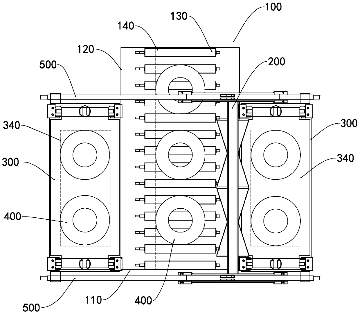
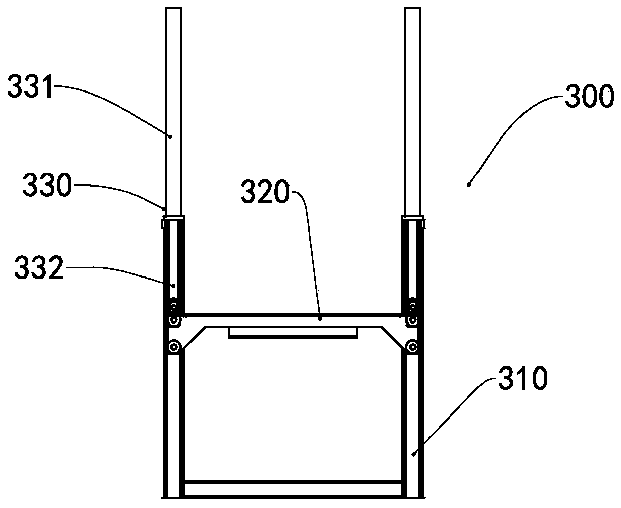
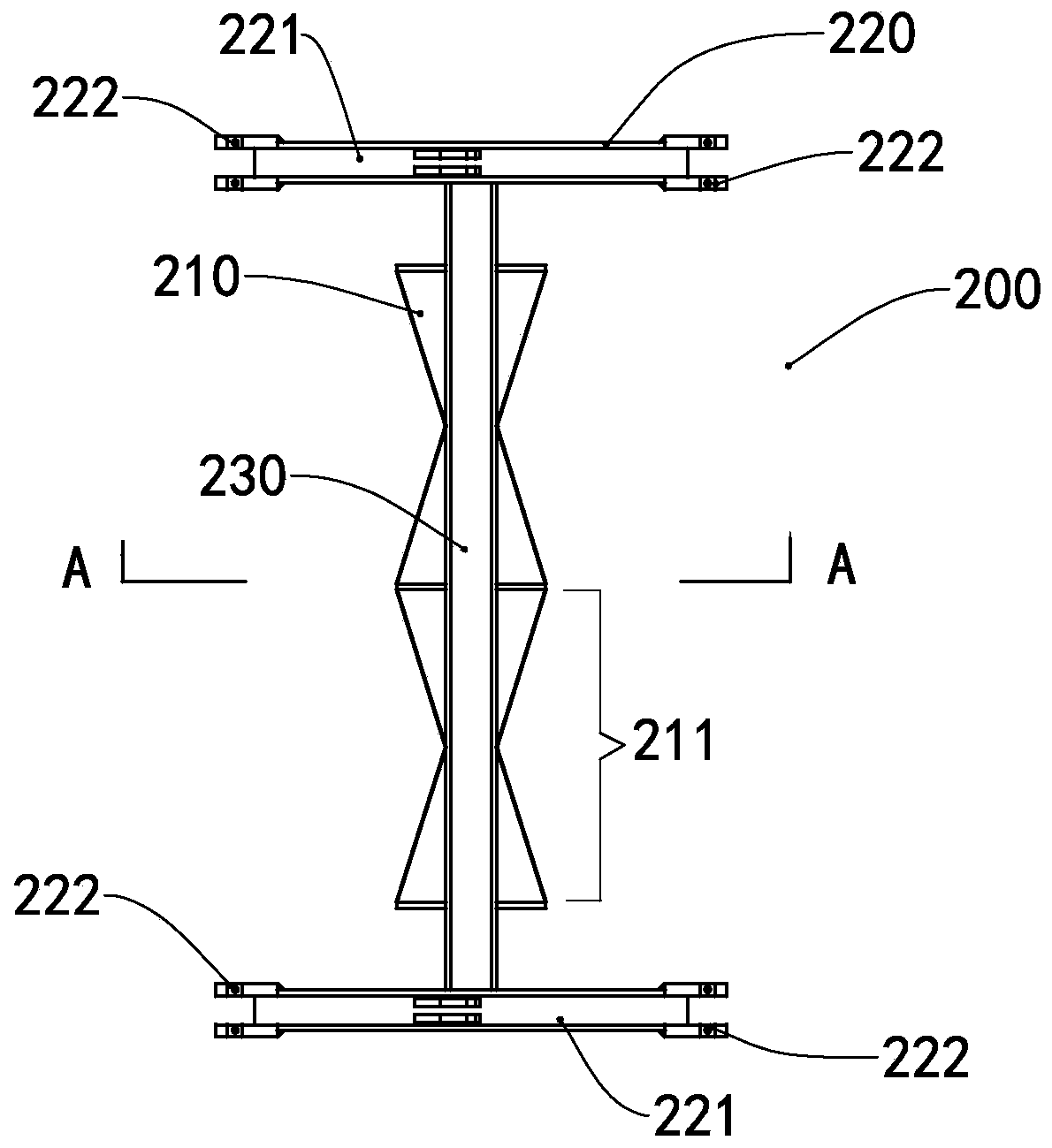
[0025] Such as figure 1 As shown, the automatic unloading device of this embodiment includes a conveying mechanism 100 , a pushing mechanism 200 and a receiving mechanism 300 . The conveying mechanism 100 includes an unloading section 110 , and the unloading section 110 is arranged at the end of the conveying direction of the conveying mechanism 100 . The conveying mechanism 100 is mainly composed of a roller frame 120 and a roller 130 arranged on the roller frame 120 . There are two receiving mechanisms 200 , which are respectively arranged on both sides of the unloading section 110 . The pushing mechanism 200 is arranged above the unloading section 110 and can move laterally perpendicular to the conveying direction of the conveying mechanism 100 . The distance between the lower end surface of the pushing mechanism 100 and the upper end surface of the blanking section 110 is greater than or equal to zero and less than the thickness of the workpiece 400 , so that the pushing...


PUM


Abstract

The invention relates to an automatic discharging device comprising a conveying mechanism, a pushing mechanism and receiving mechanisms. The conveying mechanism comprises a discharging section; the two receiving mechanisms are arranged on the two sides of the discharging section; the pushing mechanism is arranged above the discharging section and can move in the transverse direction perpendicularto the conveying direction of the conveying mechanisms; the distance between the lower end surface of the pushing mechanism and the upper end surface of the discharging section is greater than or equal to zero and is smaller than the thickness of workpieces; and the two sides of the pushing mechanism are used for pushing the workpieces. The automatic discharging device can realize automatic, efficient and rapid discharging of the workpieces of flange end plates, and the production efficiency is improved.

Description

technical field [0001] The invention relates to the technical field of automation equipment, in particular to an automatic unloading device. Background technique [0002] The flange end plate is an important part of the pipe pile, usually in the form of a ring, and is mainly used for the connection of the pipe pile. At present, the billet of the end plate is mainly produced by hot rolling and hot bending process. During the processing, the steel billet is extruded and wound by the hot bending machine to form a spring-shaped end plate coil. The end plate coil is cut and processed to obtain a single end plate blank. The notch of the blank needs to be welded, and the end plate needs to be leveled by spinning to form a flat annular disk. At present, in the above process, the conveying and blanking of end plate blanks or end plates usually requires workers to operate with the help of machines, etc., which cannot be done automatically, and only one workpiece can be unloaded at a ...

Claims


Application Information

Patent Timeline
Patent Type & Authority Applications(China)
IPC IPC(8): B65G47/82B65G47/34B65G13/00
CPCB65G13/00B65G47/34B65G47/82
Inventor 蒋科杨向东胡泳涛尹定红樊金标赵波卢文德刘烨龚继林梁志昌张燕航刘洁文春鱼曾德发
Owner 中山市六六六智能装备有限公司
Why Eureka
Try Eureka