Shale oil horizontal well deployment method and device
A technology for horizontal wells and shale oil, which is applied in the field of shale oil horizontal well deployment methods and devices, and can solve the problems of deploying shale oil horizontal wells in fault zones
- Summary
- Abstract
- Description
- Claims
- Application Information
AI Technical Summary
Problems solved by technology
Method used
Image
Examples
Embodiment 1
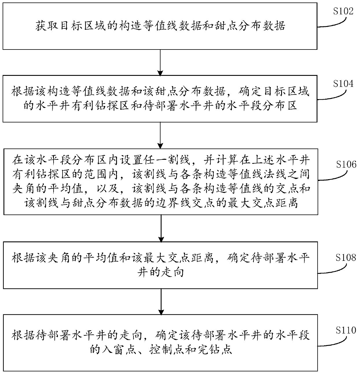
[0032] Such as figure 1 As shown, it is a schematic flow chart of a shale oil horizontal well deployment method provided by an embodiment of the present invention. figure 1 Visible, this method comprises the following steps:
[0033] Step S102: Obtain the structural contour data and sweet spot distribution data of the target area.
[0034] Here, the target area is an area within which horizontal wells are to be deployed. For this embodiment, the target area may be an area predicted to contain shale oil. In addition, structural contours are also called structural contours, and a structural contour map is a map that uses contour lines on a certain structural surface to represent its underground structure. This kind of map is similar to the topographic map showing the undulation of the ground, so its compilation principle is also similar to the topographic map. The structural contour map has the following characteristics:
[0035] ① The structural contour line essentially repr...
Embodiment 2
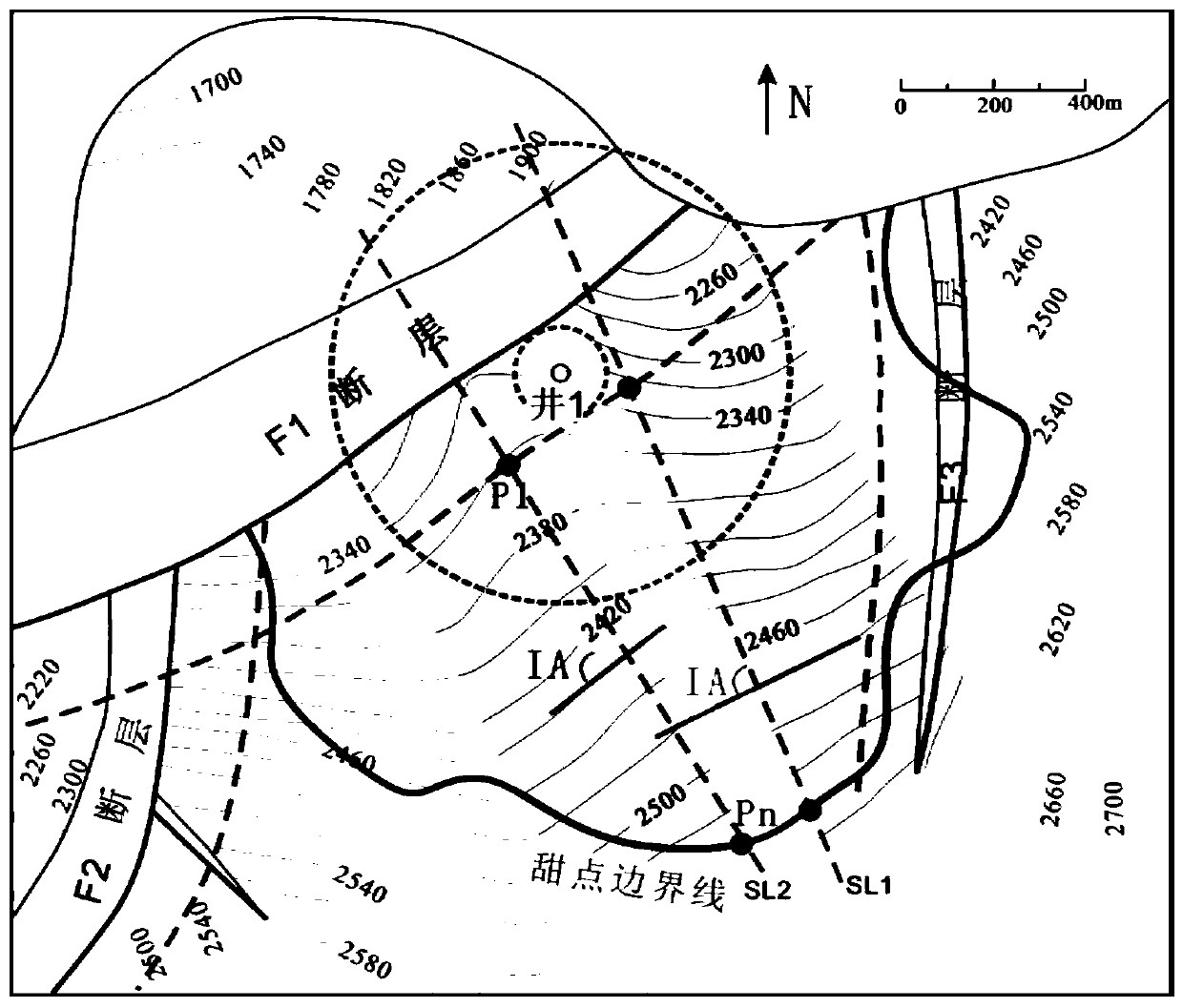
[0085] In order to better understand the above-mentioned shale oil horizontal well deployment method, this embodiment uses an application example to illustrate. Wherein, the shale oil horizontal well deployment method shown in this example mainly includes the following three steps:
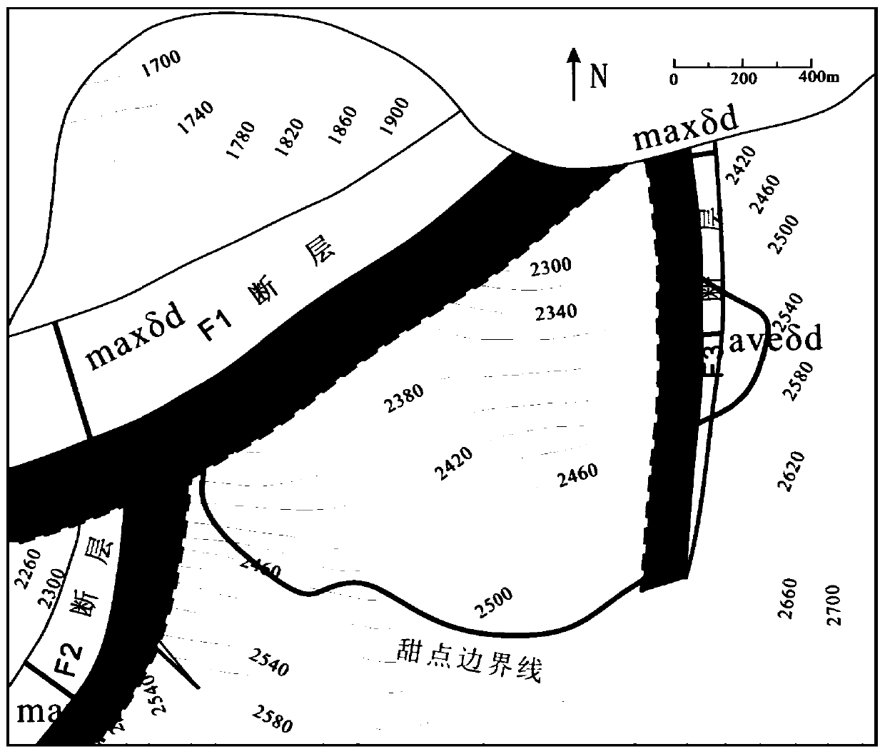
[0086] 1) Use the structural contour map and fracture distribution map to exclude unfavorable engineering fracturing areas.
[0087] ① Determine fault distribution and fault throw. There are three faults in the research area, namely F1 fault, F2 fault and F3 fault. First, calculate the maximum fault throw (δ d-max ) and average fault distance (δ d-ave ): F1 Fault: δ d-max is 482m, δ d-ave 402m; F2 fault: δ d-max is 215m, δ d-ave 137m; F3 fault: δ d-max is 83m, δ d-ave It is 52m.
[0088] ② Determine the scope of fracture influence. F1 fault, F2 fault and F3 fault δ d-max and δ d-ave They are respectively substituted into the calculation formula IA=0.2073δd+140.16 of ...
Embodiment 3
[0105] The embodiment of the present invention also provides a shale oil horizontal well deployment device, such as Figure 5 As shown, the device includes a sequentially connected data acquisition module 51, a horizontal well favorable drilling area and a horizontal section distribution area determination module 52, a horizontal well direction determination module 53 and a horizontal section parameter determination module 54, wherein the functions of each module are as follows:
[0106] A data acquisition module 51, configured to acquire structural contour data and sweet spot distribution data of the target area;
[0107] The horizontal well favorable drilling area and the horizontal section distribution area determination module 52 are used to determine the horizontal well favorable drilling area in the target area and the horizontal section distribution area of the horizontal well to be deployed according to the structural contour data and the sweet spot distributio...
PUM
 Abstract
Description
Claims
Application Information
 - R&D
- Intellectual Property
- Life Sciences
- Materials
- Tech Scout
- Unparalleled Data Quality
- Higher Quality Content
- 60% Fewer Hallucinations
Browse by: Latest US Patents, China's latest patents, Technical Efficacy Thesaurus, Application Domain, Technology Topic, Popular Technical Reports.
© 2025 PatSnap. All rights reserved.Legal|Privacy policy|Modern Slavery Act Transparency Statement|Sitemap|About US| Contact US: help@patsnap.com


