Vortex SAR imaging method and system based on orbital angular momentum

A technology of orbital angular momentum and imaging method, which is applied in the direction of radio wave measurement system, measurement device, radio wave reflection/reradiation, etc., to achieve the effect of two-dimensional imaging

Active Publication Date: 2019-11-08
NAT UNIV OF DEFENSE TECH
View PDF9 Cites 11 Cited by
  • Summary
  • Abstract
  • Description
  • Claims
  • Application Information

AI Technical Summary

Problems solved by technology

In addition, vortex SAR imaging combined with vortex electromagnetic wave and SAR imaging technology has gradually attracted attention, but related research is still in its infancy, and there are many fundamental problems to be solved urgently in terms of imaging principles, imaging models and methods.

Method used


Image

  • Vortex SAR imaging method and system based on orbital angular momentum
  • Vortex SAR imaging method and system based on orbital angular momentum
  • Vortex SAR imaging method and system based on orbital angular momentum

Examples


Embodiment Construction

[0018] The present invention will be described in detail below in conjunction with specific embodiments.

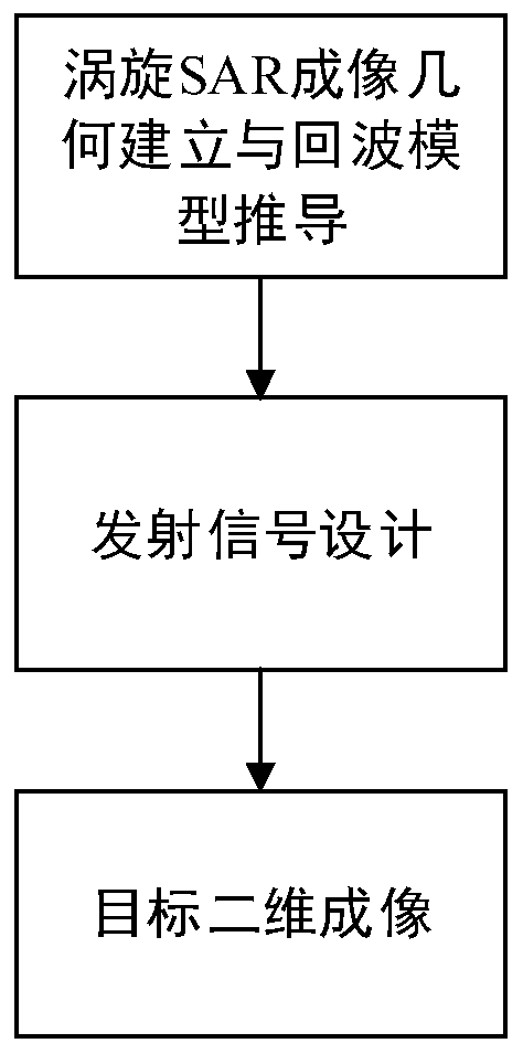
[0019] The invention provides a SAR two-dimensional imaging method based on vortex electromagnetic waves, such as figure 1 The steps shown in the flowchart are as follows.

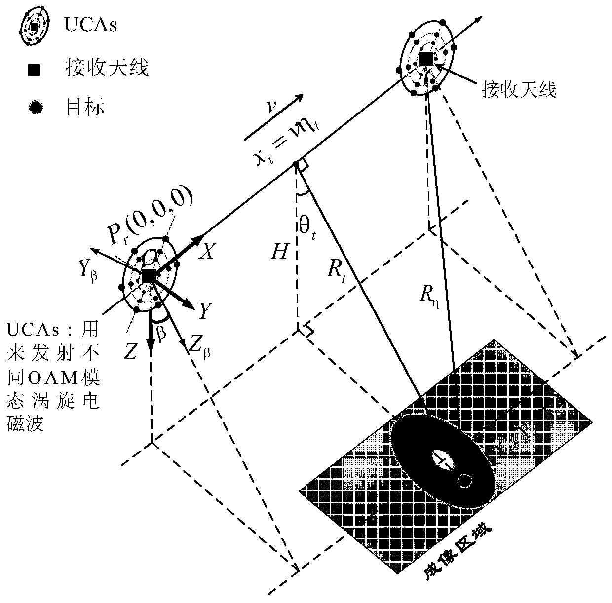
[0020] In the first step, the imaging geometric scene is established. Uniform concentric circular ring array antenna UCAs of the radar, located at XOY of the Cartesian coordinate system β In the plane, it flies at a height H above the ground at a speed v, and is used to generate vortex electromagnetic waves of different OAM modes. The direction of the X-axis is consistent with the direction of the radar movement speed v, which is defined as the azimuth direction, Z β The axis direction is consistent with the front normal direction, Y β The axis direction is then determined (satisfying the right-hand rule). At the same time, the receiving antenna is located at the center O of the UCAs, which is re...


PUM


Abstract

The invention relates to the field of radar imaging, in particular to an SAR two-dimensional imaging method and system based on a vortex electromagnetic wave. The imaging method comprises the steps that according to the characteristic of the vortex electromagnetic wave, in combination with a geometrical relationship and work mode of traditional SAR imaging, a new-system radar imaging model is constructed, transmitting and receiving modes of the vortex electromagnetic wave are selected, scene, radar and target parameters are set, and after a transmitted signal is radiated by an array antenna and interacts with a target, an echo equation is obtained through derivation; in the distance direction, by designing and generating a signal with a large time-bandwidth product, target distance-direction high-resolution information is acquired. Based on a target information add-in item introduced into an echo by the vortex electromagnetic wave, a criterion function representing that the OAM mode number carried by the vortex electromagnetic wave changes with slow time is mainly designed; finally, vortex SAR two-dimensional imaging based on the orbital angular momentum is achieved, and the new-system imaging radar with combination of the vortex electromagnetic wave and an SAR imaging technology is utilized for achieving high-azimuth-resolution two-dimensional imaging.

Description

technical field [0001] The invention relates to the field of radar imaging, in particular to a SAR two-dimensional imaging method and imaging system based on vortex electromagnetic waves. Background technique [0002] Synthetic Aperture Radar (SAR) has the ability to achieve high-resolution imaging of targets in the detection area under all-weather, all-weather, and severe weather conditions. Two-dimensional imaging using traditional plane waves is mainly based on the range-Doppler principle, namely In the radar velocity direction (azimuth direction), a large virtual equivalent antenna aperture is formed through motion, and the high-resolution imaging result of the target azimuth direction is obtained by using signal processing methods. In the range direction, according to the dual relationship between the distance position of the target relative to the radar and the frequency of the transmitted signal, a large time-bandwidth product signal, such as a linear frequency modula...

Claims


Application Information

Patent Timeline
Patent Type & Authority Applications(China)
IPC IPC(8): G01S13/90
CPCG01S13/90G01S13/9082
Inventor 刘康王建秋程永强王宏强蒋彦雯刘红彦
Owner NAT UNIV OF DEFENSE TECH
Why Eureka
Try Eureka