Parameter-based dynamic geometric three-dimensional graph cutting implementation method

A technology of dynamic geometry and three-dimensional graphics, applied in animation production, image data processing, instruments, etc., can solve the problems of inability to cut and dynamically control the cutting rate, etc.

Active Publication Date: 2019-11-08
CHENGDU JINGZHONG EDUCATIONAL SOFTWARE CO LTD
View PDF8 Cites 2 Cited by
  • Summary
  • Abstract
  • Description
  • Claims
  • Application Information

AI Technical Summary

Problems solved by technology

[0003] The purpose of the present invention is to provide a parameter-based method for realizing dynamic geometric three-dimensional graphics cutting, which is used to solve the problems in the prior art that multiple cutting planes cannot be used to cut three-dimensional graphics, and the cutting rate cannot be dynamically controlled by parameters

Method used


Image

  • Parameter-based dynamic geometric three-dimensional graph cutting implementation method
  • Parameter-based dynamic geometric three-dimensional graph cutting implementation method
  • Parameter-based dynamic geometric three-dimensional graph cutting implementation method

Examples


Embodiment 1

[0035] Attached figure 1 As shown, a parameter-based dynamic geometric 3D graphics cutting realization method includes:

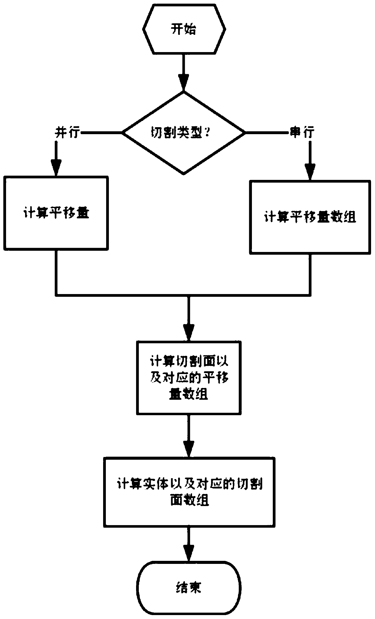
[0036] Step S100: Set cutting parameters, the cutting parameters include a cutting surface and a cutting type, the cutting control variable is a variable associated with the cutting animation; the cutting displacement is the maximum displacement of the cutting animation; the cutting surface is one or more planes; Cutting types include serial cutting and parallel cutting. Serial cutting is multiple cutting surfaces to sequentially cut the cut three-dimensional graphics; parallel cutting is multiple cutting surfaces to simultaneously cut the cut three-dimensional graphics;

[0037] Step S200: Determine the amount of movement of the cut three-dimensional figure during the cutting process according to the cutting control variable and the cutting displacement, determine the movement direction of the cut three-dimensional figure during the cutting animation according t...

Embodiment 2

[0042] Further, the step S200 specifically includes:

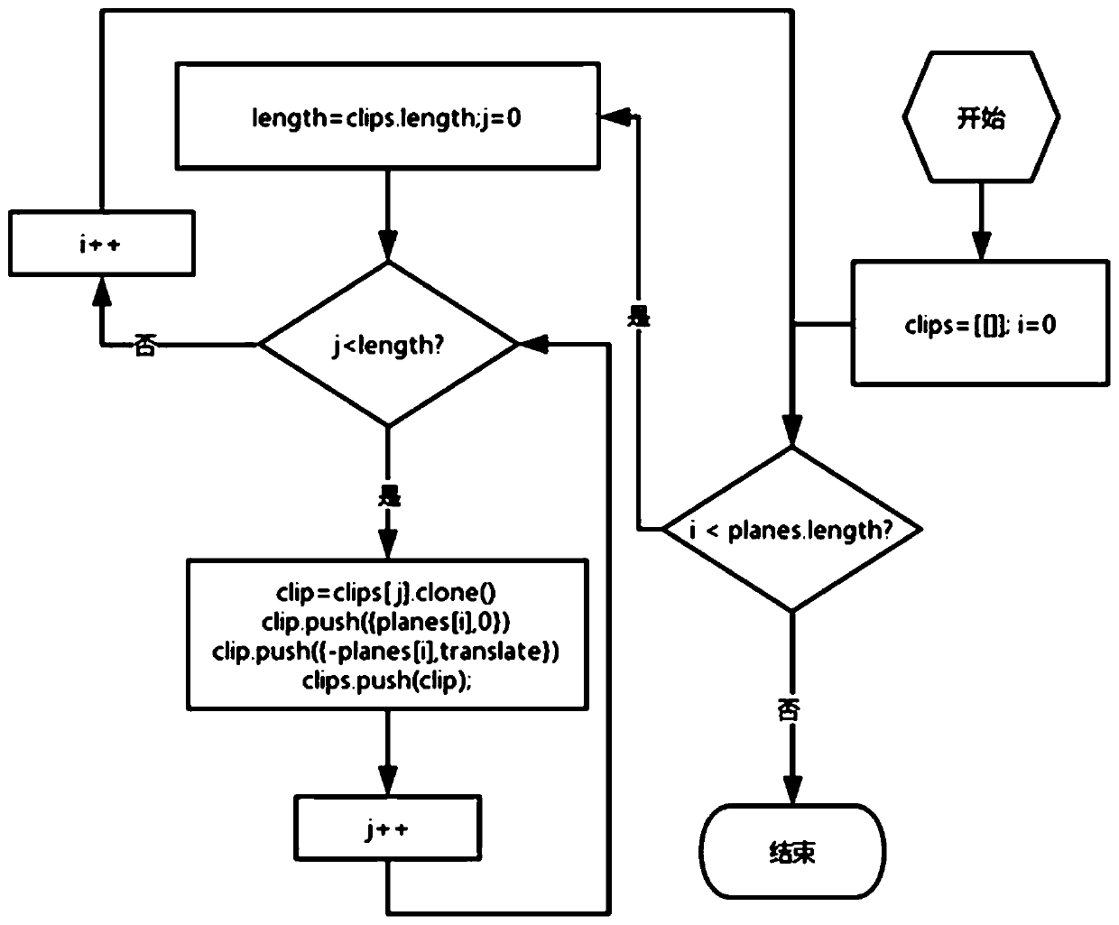
[0043] Step S210: Calculate the translation amount, the translation amount array, the cutting surface and the corresponding translation amount array;

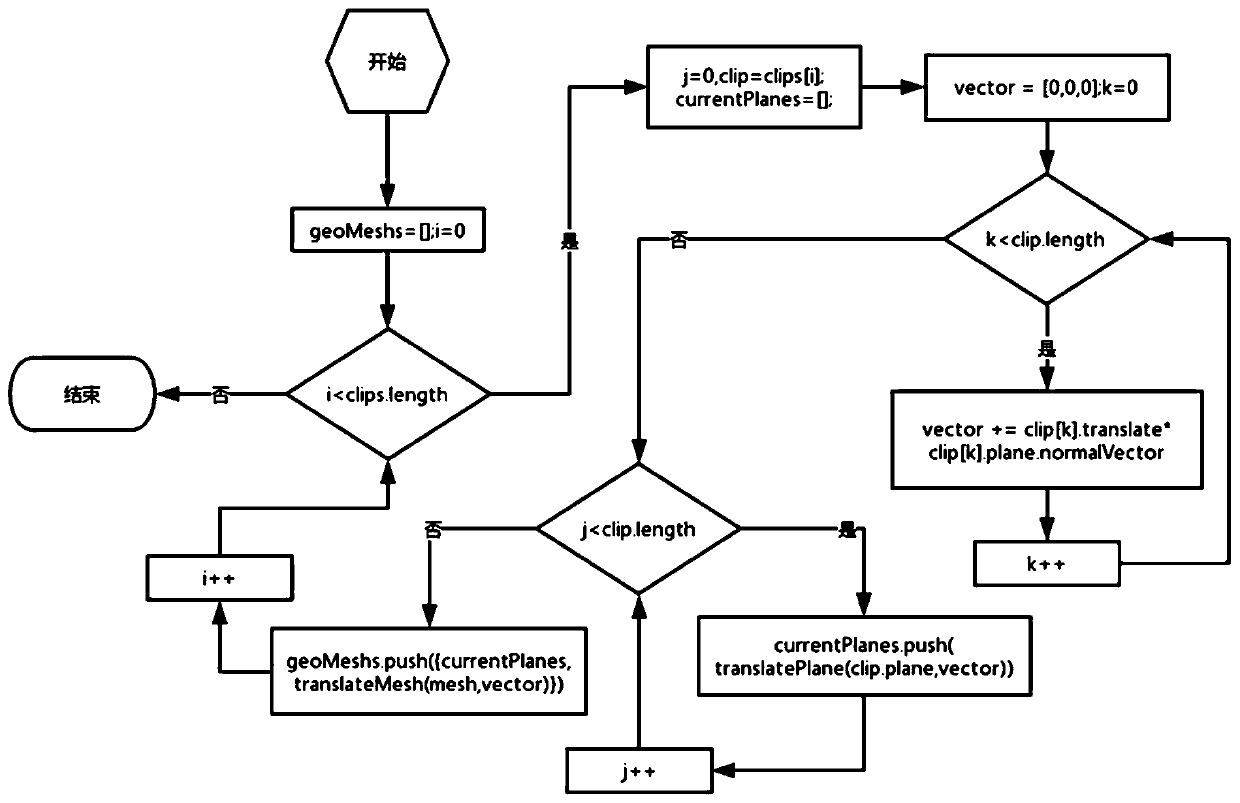
[0044] Step S220: Calculate the three-dimensional graphics and the corresponding cutting surface array;

[0045] Step S230: During the cutting process, the three-dimensional graphics are dynamically displayed according to the translation amount or the translation array, the cutting surface and the corresponding translation amount array, and the three-dimensional graphics and the corresponding cutting surface array.

[0046] If it is a parallel cutting, you need to calculate the vector distance of the translation of all the cutting surfaces according to the cutting parameters, that is, the translation amount. Because of the parallel cutting, the vector distance of the translation of all the cutting surfaces is the same, so you only need to calculate it once, and then the translation ...


PUM


Abstract

The invention discloses a parameter-based dynamic geometric three-dimensional graph cutting implementation method, which comprises the following steps of: setting cutting attributes which comprise a cutting plane, a cutting type, a cutting control variable and cutting displacement, and the cutting control variable is a variable associated with a cutting animation; the cutting displacement is the maximum displacement of the cutting animation; the cutting surfaces are one or more planes, and the cutting types comprise serial cutting and parallel cutting; and the movement amount of the cut three-dimensional graph in the cutting process is determined according to the cutting control variable and the cutting displacement, the normal direction of the cutting surface determines the animation cutting direction of the cut three-dimensional graph on the plane, and the cutting process of the three-dimensional graph is dynamically displayed. According to the method, the multiple cutting surfaces are used for cutting the three-dimensional graph, the cutting rate is dynamically controlled through the parameters to achieve the dynamic cutting effect, the cutting sequence is expanded, parallel cutting and serial cutting are included and selected by a user, persuasion is better achieved, and the teaching requirement is met.

Description

Technical field [0001] The invention relates to the technical field of dynamic geometric application software, and specifically, is a parameter-based method for realizing cutting of dynamic geometric three-dimensional graphics. Background technique [0002] Dynamically drag the free points in the geometric figures to vividly obtain the dynamic process of the geometric figures maintaining the constraint relationship, so as to better understand the geometric properties contained in the geometric figures. A system with such characteristics is called dynamic geometry. Dynamic geometry is an important application of geometric constraint solving. It is widely used in teaching aids and is an educational information tool for in-depth basic mathematics. 3D dynamic geometry software is education-oriented solid geometry teaching assistant software. Using this kind of software for assistant teaching can intuitively establish real 3D space and solid graphics. In three-dimensional geometry, i...

Claims


Application Information

Patent Timeline
Patent Type & Authority Applications(China)
IPC IPC(8): G06T19/20G06T13/20G09B19/00
CPCG06T19/20G06T13/20G09B19/00
Inventor 冯清尧刚张中文张景中何义兵林咏渔管皓
Owner CHENGDU JINGZHONG EDUCATIONAL SOFTWARE CO LTD
Why Eureka
Try Eureka