Switch cabinet with automatic fire extinguishing function
An automatic fire extinguishing and switchgear technology, which is applied in the field of switchgear, can solve problems such as motor magnetic switch damage, achieve the effects of reducing vibration, ensuring normal operation, and improving service life
- Summary
- Abstract
- Description
- Claims
- Application Information
AI Technical Summary
Problems solved by technology
Method used
Image
Examples
Embodiment 1
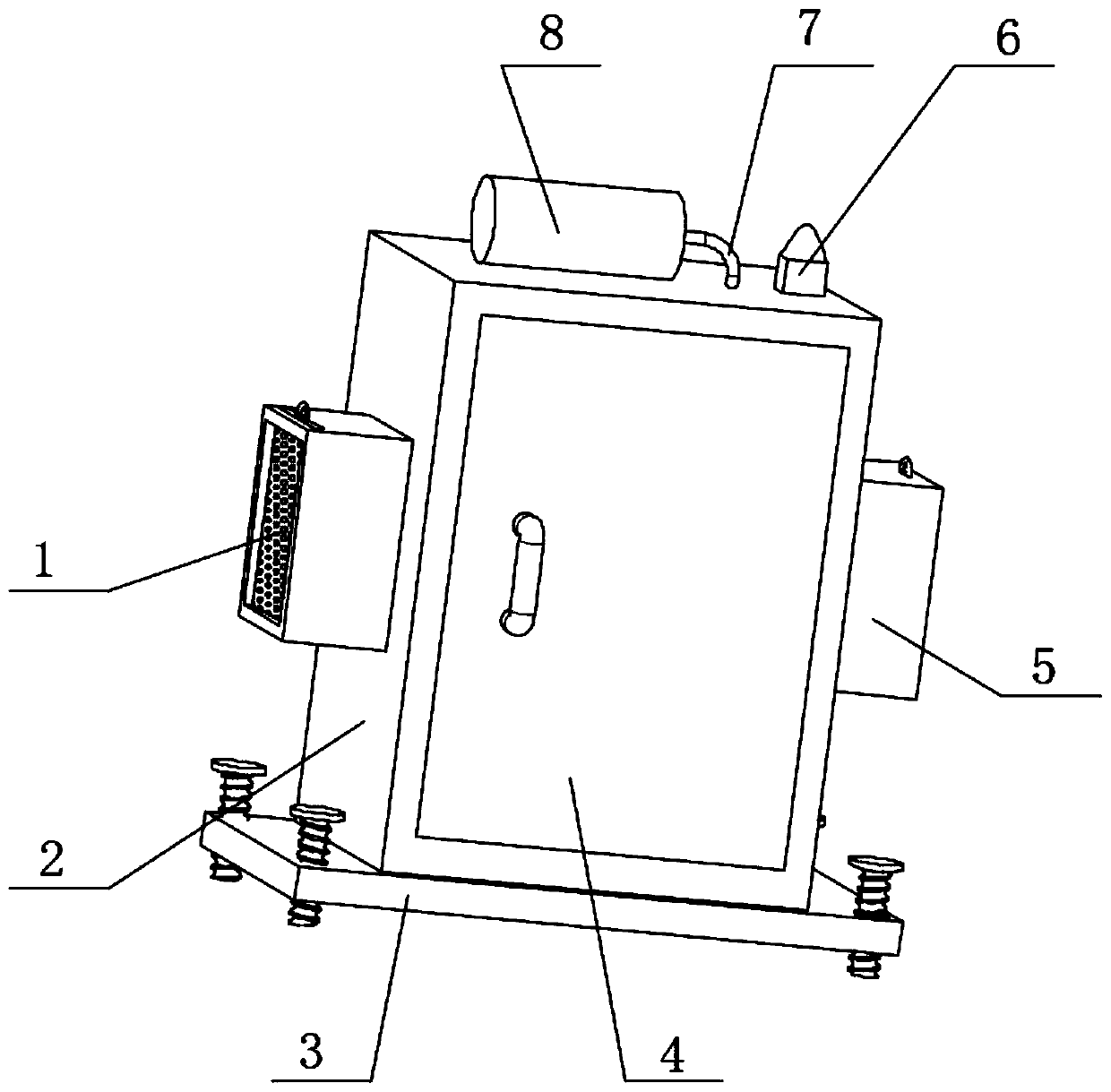
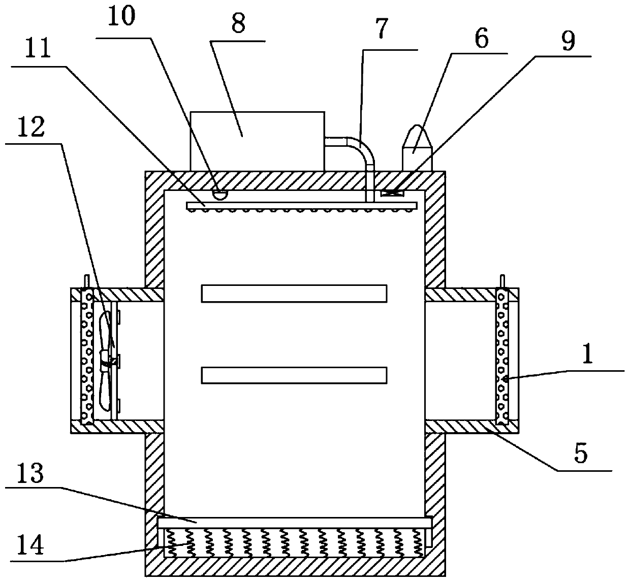
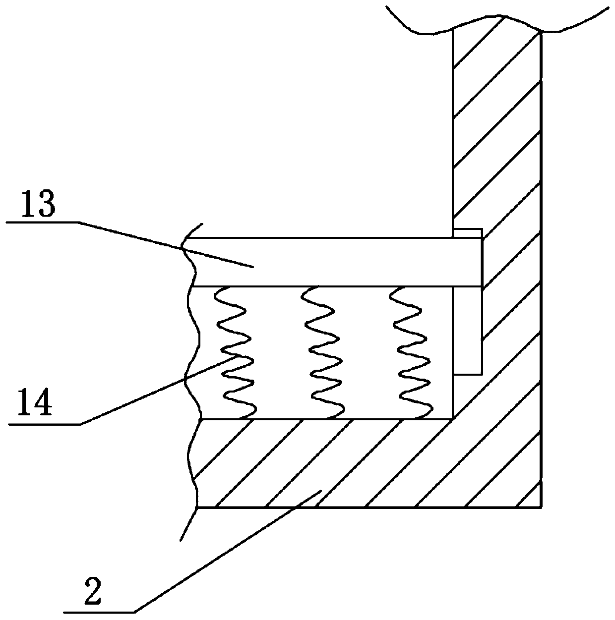
[0024] refer to Figure 1-3 , a switch cabinet with automatic fire extinguishing function, comprising a cabinet body 2, a fire extinguisher 8 is installed on the outer wall of the top of the cabinet body 2, and an outlet pipe 7 is installed at the output end of the fire extinguisher 8, and the other end of the outlet pipe 7 extends to the inside of the cabinet body 2, The inwall of air outlet pipe 7 is equipped with a solenoid valve, and the outer wall of the bottom of air outlet pipe 7 is equipped with an air jet pipe 11, and the outer wall of the bottom of the air outlet pipe 11 is equipped with equidistantly distributed air nozzles, and the outer wall of one side of the top of the cabinet body 2 is equipped with a smoke sensor 10, and A processor 9 is installed on the inner wall on the other side of the top of the cabinet 2. The model of the processor 9 is ARM9TDMI. The smoke sensor 10 is electrically connected to the signal input end of the processor 9 through a signal line...
Embodiment 2
[0029] refer to Figure 1-4 , a switchgear with an automatic fire extinguishing function, further comprising a cover plate 15 plugged into the outer wall on one side of the top of two installation shells 5, and a second sliding groove 16 is opened on the top of the outer wall on both sides of the installation shell 5, The inner wall of the second sliding groove 16 is slidably connected with a sliding block, the outer wall on one side of the sliding block is fixedly connected to the top of the outer wall on one side of the cover plate 15, and the top of the outer wall on one side of the housing 5 is installed with a riser 19, and the outer wall on one side of the riser 19 An electric telescopic rod 18 is installed, and a connection plate 17 is installed at the output end of the electric telescopic rod 18 .
[0030] Working principle: Compared with Embodiment 1, the electric telescopic rod 18 is electrically connected to the processor 9 through wires, and is provided with a cove...
PUM
 Abstract
Description
Claims
Application Information
 - R&D
- Intellectual Property
- Life Sciences
- Materials
- Tech Scout
- Unparalleled Data Quality
- Higher Quality Content
- 60% Fewer Hallucinations
Browse by: Latest US Patents, China's latest patents, Technical Efficacy Thesaurus, Application Domain, Technology Topic, Popular Technical Reports.
© 2025 PatSnap. All rights reserved.Legal|Privacy policy|Modern Slavery Act Transparency Statement|Sitemap|About US| Contact US: help@patsnap.com


