
Service node fault self-healing method, device, computer equipment and storage medium

A service node, fault self-healing technology, applied in digital transmission systems, electrical components, transmission systems, etc., can solve the problems of access failure, inability to achieve automatic detection and automatic self-healing, long fault repair time, etc., to ensure fast effect of response

Pending Publication Date: 2019-11-08
云南电网有限责任公司信息中心
View PDF13 Cites 22 Cited by
  • Summary
  • Abstract
  • Description
  • Claims
  • Application Information

AI Technical Summary

Problems solved by technology

[0002] Currently, the CSGII system uses the load balancing device in the active / standby / cold standby mode, that is, each system consumes two load balancing devices, and one of the standby machines uses the cold standby mode, and the load capacity of the standby machine is idle for a long time. Since the current load balancing health check can only be performed on the server level and cannot be checked on the business level, it often happens that the server is running normally, but the program that provides services on the server is abnormal, and the load balancing device will still allocate business requests to the server, resulting in access failure.
Employees often cannot access their own financial platform, which seriously affects the development of daily reimbursement and other work
[0003] At present, the faults of service nodes can only be manually checked and eliminated, and automatic detection and self-healing cannot be achieved, resulting in a long time for fault repair, and it is difficult to accurately find specific problems of service node faults, which leads to a low success rate of fault repair

Method used


Image

  • Service node fault self-healing method, device, computer equipment and storage medium
  • Service node fault self-healing method, device, computer equipment and storage medium
  • Service node fault self-healing method, device, computer equipment and storage medium

Examples


Embodiment Construction

[0063] The following will clearly and completely describe the technical solutions in the embodiments of the present invention with reference to the accompanying drawings in the embodiments of the present invention. Obviously, the described embodiments are part of the embodiments of the present invention, but not all of them. Based on the embodiments of the present invention, all other embodiments obtained by persons of ordinary skill in the art without making creative efforts belong to the protection scope of the present invention.

[0064] It should be understood that when used in this specification and the appended claims, the terms "comprising" and "comprises" indicate the presence of described features, integers, steps, operations, elements and / or components, but do not exclude one or Presence or addition of multiple other features, integers, steps, operations, elements, components and / or collections thereof.

[0065] It should also be understood that the terminology used in...


PUM


Abstract

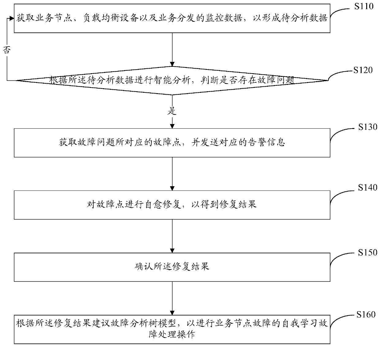
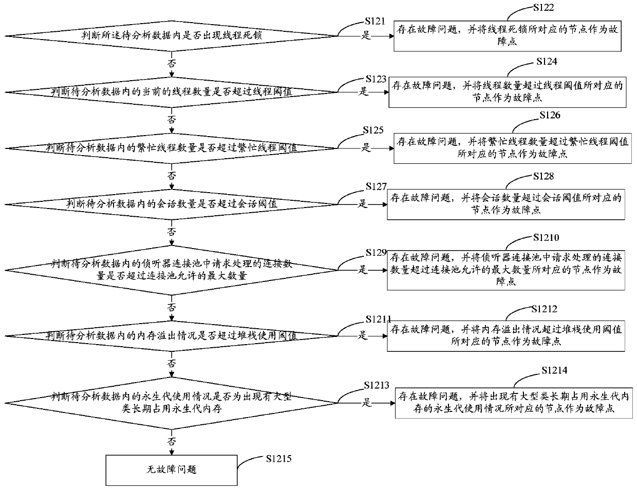
The invention relates to a service node fault self-healing method, a device, computer equipment and a storage medium. The method comprises the steps: obtaining monitoring data of a service node, loadbalancing equipment and service distribution, so as to form to-be-analyzed data; performing intelligent analysis according to the to-be-analyzed data, and judging whether a fault problem exists or not; if yes, a fault point corresponding to the fault problem is obtained, and corresponding alarm information is sent; performing self-healing repair on the fault point to obtain a repair result; acknowledging repair results. According to the invention, multi-aspect detection is carried out on the service nodes, the system and the database. When a fault problem occurs, a corresponding self-healing script is automatically called. The self-healing script is remotely executed to self-heal and repair the fault problem. The fault analysis tree model is generated according to the repair result. The subsequent nodes can perform self-learning repair according to the fault analysis tree model. The health state of the service nodes is detected in real time. The service nodes with faults are subjectedto self-healing repair to ensure that the user request can quickly respond.

Description

technical field [0001] The invention relates to a self-healing method for a power communication network, and more specifically refers to a service node fault self-healing method, device, computer equipment and storage medium. Background technique [0002] Currently, the CSGII system uses the load balancing device in the active / standby / cold standby mode, that is, each system consumes two load balancing devices, and one of the standby machines uses the cold standby mode, and the load capacity of the standby machine is idle for a long time. Since the current load balancing health check can only be performed on the server level and cannot be checked on the business level, it often happens that the server is running normally, but the program that provides services on the server is abnormal, and the load balancing device will still allocate business requests to the server, resulting in access failure. . Employees often cannot access their own financial platform, which seriously a...

Claims


Application Information

Patent Timeline
IPC IPC(8): H04L12/24H04L12/26
CPCH04L41/0654H04L41/0681H04L43/16H04L43/0817H04L41/0677H04L41/0636
Inventor 漆振飞钏涛吕垚彭晓平罗华峰
Owner 云南电网有限责任公司信息中心
Learn More