Steel wire cutter for building

A cutter and steel wire technology, applied in metal processing, metal processing equipment, manufacturing tools, etc., can solve the problems of steel wire bending deformation, low degree of automation, and low work efficiency, so as to speed up cutting, facilitate storage and use, The effect of high work efficiency

Active Publication Date: 2019-11-12
DONGYANG LUOSU ELECTRONICS TECH CO LTD
View PDF9 Cites 4 Cited by
  • Summary
  • Abstract
  • Description
  • Claims
  • Application Information

AI Technical Summary

Problems solved by technology

[0002] The traditional steel wire cutting work cuts the steel wire through the force of the hydraulic cylinder to drive the cutting knife to press down. Not only does it require a large downward force, but it is only suitable for cutting hard and brittle materials, and the application range is small. Secondly, the traditional steel wire cutting device usually requires Manpower assists in conveying the steel wire, the degree of automation is low, and the steel wire is not fixed. During the thick cutting process, the pressure of the cutting knife will make the steel wire bend and deform, and at the same time affect the force direction of the cutting knife, resulting in low cutting accuracy and low work efficiency. And the steel wire after cutting is not equipped with a counting device, which needs to be manually counted and counted, and the device is inconvenient to use

Method used


Image

  • Steel wire cutter for building
  • Steel wire cutter for building
  • Steel wire cutter for building

Examples


Embodiment Construction

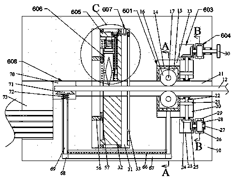
[0023] Combine below Figure 1-Figure 6 The present invention is described in detail, and for convenience of description, the orientations mentioned below are now stipulated as follows: figure 1 The up, down, left, right, front and back directions of the projection relationship itself are the same.

[0024] The present invention relates to a kind of steel wire cutter used in construction, which is mainly used for steel wire cutting work. The present invention will be further described below in conjunction with the accompanying drawings of the present invention:

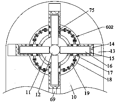
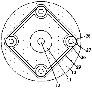
[0025]A steel wire cutter for construction according to the present invention includes a cutting body 10, and a conveying hole 11 is arranged inside the cutting body 10, a steel wire 12 is placed in the conveying hole 11, and a steel wire 12 is placed outside the conveying hole 11. Conveying device 601, including four conveying wheels 16 in the conveying device 601, power connection between the conveying wheels 16 th...


PUM


Abstract

The invention discloses a steel wire cutter for building. The steel wire cutter comprises a cutting machine body, wherein a conveying hole is formed in the cutting machine body, a steel wire is arranged in the conveying hole, a conveying device is arranged on the outer side of the conveying hole, the conveying device comprises four conveying wheels, the conveying wheels are in power connection through a transmission device, and a clamping and adjusting device is arranged on the right side of the conveying device, and can drive the conveying wheels to move oppositely. According to the steel wire cutter, the steel wire is conveyed, clamped and fixed through the four conveying wheels of a annular array, so that the position of the steel wire is stable in a cutting process, in the cutting process, a cutting knife rotates in the circumferential direction of the steel wire for annular cutting, the cutting knife rotates on the axis of the cutting knife and rotatably cuts the steel wire alongthe surface to the interior of the steel wire, the cutting speed is increased, the cutting working efficiency is high, and a counting device is arranged in the cutter.

Description

technical field [0001] The invention relates to the technical field of steel wire cutting, in particular to a steel wire cutter for construction. Background technique [0002] The traditional steel wire cutting work cuts the steel wire through the force of the hydraulic cylinder to drive the cutting knife to press down. Not only does it require a large downward force, but it is only suitable for cutting hard and brittle materials, and the application range is small. Secondly, the traditional steel wire cutting device usually requires Manpower assists in conveying the steel wire, the degree of automation is low, and the steel wire is not fixed. During the thick cutting process, the pressure of the cutting knife will make the steel wire bend and deform, and at the same time affect the force direction of the cutting knife, resulting in low cutting accuracy and low work efficiency. And the cut steel wire is not equipped with a counting device, which needs to be manually counted ...

Claims


Application Information

Patent Timeline
Patent Type & Authority Applications(China)
IPC IPC(8): B21F11/00B21F23/00B21C51/00
CPCB21C51/00B21F11/00B21F23/00
Inventor 陈婉丽
Owner DONGYANG LUOSU ELECTRONICS TECH CO LTD
Why Eureka
Try Eureka