
Brake device for rail traffic

A braking device and track technology, applied in the field of track braking, can solve the problems of wheel and track wear, lack of braking effect, and unsatisfactory braking effect, so as to reduce the severity of wear and improve safety and stability Effect

Inactive Publication Date: 2019-11-12
贾文康
View PDF6 Cites 4 Cited by
  • Summary
  • Abstract
  • Description
  • Claims
  • Application Information

AI Technical Summary

Problems solved by technology

[0003] Rail vehicles hold the wheel tread tightly when braking. The braking method is to use the friction between the wheel and the track to achieve braking. Since the contact area between the wheel and the track is relatively small, under the action of vehicle inertia, the vehicle still needs to Sliding for hundreds of meters to stop, the braking effect is not ideal, sometimes even can not achieve the braking effect, and it is easy to wear the wheels and tracks, so it is necessary to design a braking device that uses friction to achieve braking

Method used


Image

  • Brake device for rail traffic
  • Brake device for rail traffic
  • Brake device for rail traffic

Examples


Embodiment Construction

[0024] The technical solutions of the present invention will be further described below in conjunction with the accompanying drawings and through specific implementation methods.

[0025] Wherein, the accompanying drawings are only for illustrative purposes, showing only schematic diagrams, rather than physical drawings, and should not be construed as limitations on this patent; in order to better illustrate the embodiments of the present invention, some parts of the accompanying drawings will be omitted, Enlargement or reduction does not represent the size of the actual product; for those skilled in the art, it is understandable that certain known structures and their descriptions in the drawings may be omitted.

[0026] In the drawings of the embodiments of the present invention, the same or similar symbols correspond to the same or similar components; , "inner", "outer" and other indicated orientations or positional relationships are based on the orientations or positional ...


PUM


Abstract

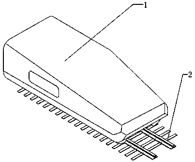
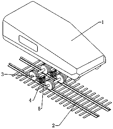
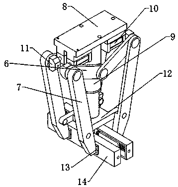
The invention relates to the field of rail brake, in particular to a brake device for rail traffic. The device comprises a bullet train and a rail, and further comprises a supporting assembly, a movable assembly and a friction assembly; the movable assembly comprises two symmetrically-arranged dual-connecting-rod mechanisms, each dual-connecting-rod mechanism comprises two symmetrically-arranged single-connecting-rod mechanism, each single-connecting-rod mechanism is composed of two short connecting rods and two long connecting rods, one ends of the short connecting rods are oppositely hingedto the middle of the outer side of the supporting assembly, one ends of the long connecting rods are oppositely hinged to the free ends of the two short connecting rods respectively, and the free endsof the long connecting rods are oppositely hinged to the lower half part of the supporting assembly separately. The problem that when the brake device brakes the bullet train, abrasion to wheels andrails are serious is solved, abrasion severity is lowered, and safety and stability are improved.

Description

technical field [0001] The invention relates to the field of rail braking, in particular to a braking device for rail transportation. Background technique [0002] Railway cars are used to pull trailers or other objects along the track. Rail transit has gradually become an important means of transportation between cities, carrying a large number of citizens' daily travel. Rail transit safety has naturally become the most important issue. Now Some railway moving car brake devices all use wheel brakes. The most common brake method used by rail vehicles is brake shoe brakes, which are tile-shaped brake blocks made of cast iron or other materials. [0003] Rail vehicles hold the wheel tread tightly when braking. The braking method is to use the friction between the wheel and the track to achieve braking. Since the contact area between the wheel and the track is relatively small, under the action of vehicle inertia, the vehicle still needs to Sliding hundreds of meters to stop, ...

Claims


Application Information

Patent Timeline
IPC IPC(8): B61H7/12
CPCB61H7/12
Inventor 贾文康
Owner 贾文康
Learn More