Yarn guide device for production of socks

A guiding device and yarn technology, applied in textiles and papermaking, weft knitting, knitting and other directions, can solve the problems of yarn drooping, knotting, affecting the working process, yarn wear, etc., achieving a simple overall structure and improving application range, the effect of ensuring the balance of force

Active Publication Date: 2019-11-12
湖南莎丽袜业股份有限公司
View PDF9 Cites 4 Cited by
  • Summary
  • Abstract
  • Description
  • Claims
  • Application Information

AI Technical Summary

Problems solved by technology

[0002] The textile machine is a weaving tool that must be used in the textile factory. The existing textile machine has been developed to a relatively high-quality level, and it has got rid of the trouble of manual processing. Before using the textile machine to weave, the yarn must be guided, otherwise the yarn The threads will be messy. If the yarns are mixed together, it will seriously affect the operation of the textile machine and affect the work process. The existing yarn guide structure needs to move on the guide column, so the yarn enters the textile There is a large amount of wear between machine weaving, and the yarn is pulled tightly by the textile drive of the textile machine during the guiding process, which is likely to cause thread breakage. When the speed of the textile drive changes, It is also prone to yarn drooping and knotting, which greatly affects the normal operation of the textile machine

Method used


Image

  • Yarn guide device for production of socks
  • Yarn guide device for production of socks

Examples


Embodiment Construction

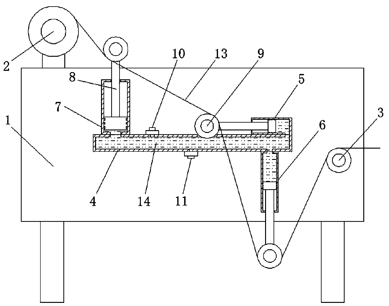
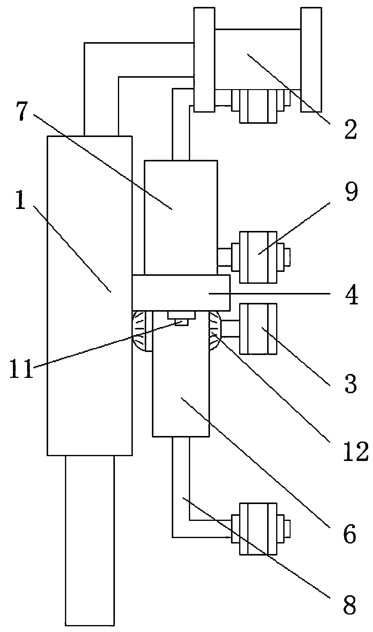
[0014] In order to facilitate the understanding of the present invention, the present invention will be described more fully below with reference to the associated drawings. A preferred embodiment of the invention is shown in the drawings. However, the present invention can be embodied in many different forms and is not limited to the embodiments described herein. Rather, these embodiments are provided so that the disclosure of the present invention will be thorough and complete.

[0015] It should be noted that when an element is considered to be “disposed” or “connected” to another element, it may be directly disposed or connected to another element or an intervening element may exist at the same time.

[0016] Unless otherwise defined, all technical and scientific terms used herein have the same meaning as commonly understood by one of ordinary skill in the technical field of the invention. The terms used in the description are only for describing specific implementation ...


PUM


Abstract

The invention relates to a yarn guide device for production of socks. The yarn guide device comprises a vertical plate, a yarn frame and a yarn outlet wheel are fixedly arranged on the vertical plate,the side wall of the vertical plate is provided with a pressure liquid cavity, and the vertical plate is provided with piston cavities which are communicated with the pressure liquid cavity. A pistonrod is arranged in each piston cavity, one end of each piston rod is slidably connected in the corresponding piston cavity, the other end of each piston rod penetrates the side wall of the corresponding piston cavity to be arranged freely, and a free end of each piston rod is provided with a guide wheel. The piston cavities include a first piston cavity in transverse arrangement and a second piston cavity in longitudinal arrangement, and the free end of the piston rod in the second piston cavity is arranged downwards. By arrangement of the pressure liquid cavity and the piston cavities, a gapof the guide wheels on the piston rods can be regulated, and accordingly the yarn length can be changed to adapt to deviation in spinning drive and guarantee yarns in a stable state constantly. The yarn guide device has advantages of simple structure, convenience in operation, extensive applicability and the like.

Description

technical field [0001] The invention relates to the technical field of textile machinery, in particular to a yarn guiding device for socks production. Background technique [0002] The textile machine is a weaving tool that must be used in the textile factory. The existing textile machine has been developed to a relatively high-quality level, and it has got rid of the trouble of manual processing. Before using the textile machine to weave, the yarn must be guided, otherwise the yarn The threads will be messy. If the yarns are mixed together, it will seriously affect the operation of the textile machine and affect the work process. The existing yarn guide structure needs to move on the guide column, so the yarn enters the textile There is a large amount of wear between machine weaving, and the yarn is pulled tightly by the textile drive of the textile machine during the guiding process, which is likely to cause thread breakage. When the speed of the textile drive changes, It...

Claims


Application Information

Patent Timeline
Patent Type & Authority Applications(China)
IPC IPC(8): D04B15/44
CPCD04B15/44
Inventor 刘晋夫李丽莎董艺姜博钟虹喻小红
Owner 湖南莎丽袜业股份有限公司
Why Eureka
Try Eureka