Large centrifugal blower

A centrifugal fan, a large-scale technology, applied in the direction of mechanical equipment, machines/engines, non-variable pumps, etc., can solve the problems of increased motor start-up vibration, motor start-up failure, breakdown, etc., to ensure force balance and reduce start-up The effect of load

Inactive Publication Date: 2017-08-29
BAOSTEEL SPECIAL STEEL CO LTD
View PDF6 Cites 4 Cited by
  • Summary
  • Abstract
  • Description
  • Claims
  • Application Information

AI Technical Summary

Problems solved by technology

When the main fan motor is started, it will trip due to the high current or the high current will break down the slip ring carbon brush of the main fan motor rotor, etc.
[0006] When the motor starts, the vibration of the motor increases due to the increase of the load. When the vibration exceeds 6.3mm / s, the motor will start to automatically protect and cut off the power, resulting in the failure of the motor to start

Method used


Image

  • Large centrifugal blower
  • Large centrifugal blower
  • Large centrifugal blower

Examples


Embodiment Construction

[0033] The present invention will be described in detail below with reference to specific embodiments. The following examples will help those skilled in the art to further understand the present invention, but do not limit the present invention in any form. It should be noted that, for those skilled in the art, several modifications and improvements can be made without departing from the concept of the present invention. These all belong to the protection scope of the present invention.

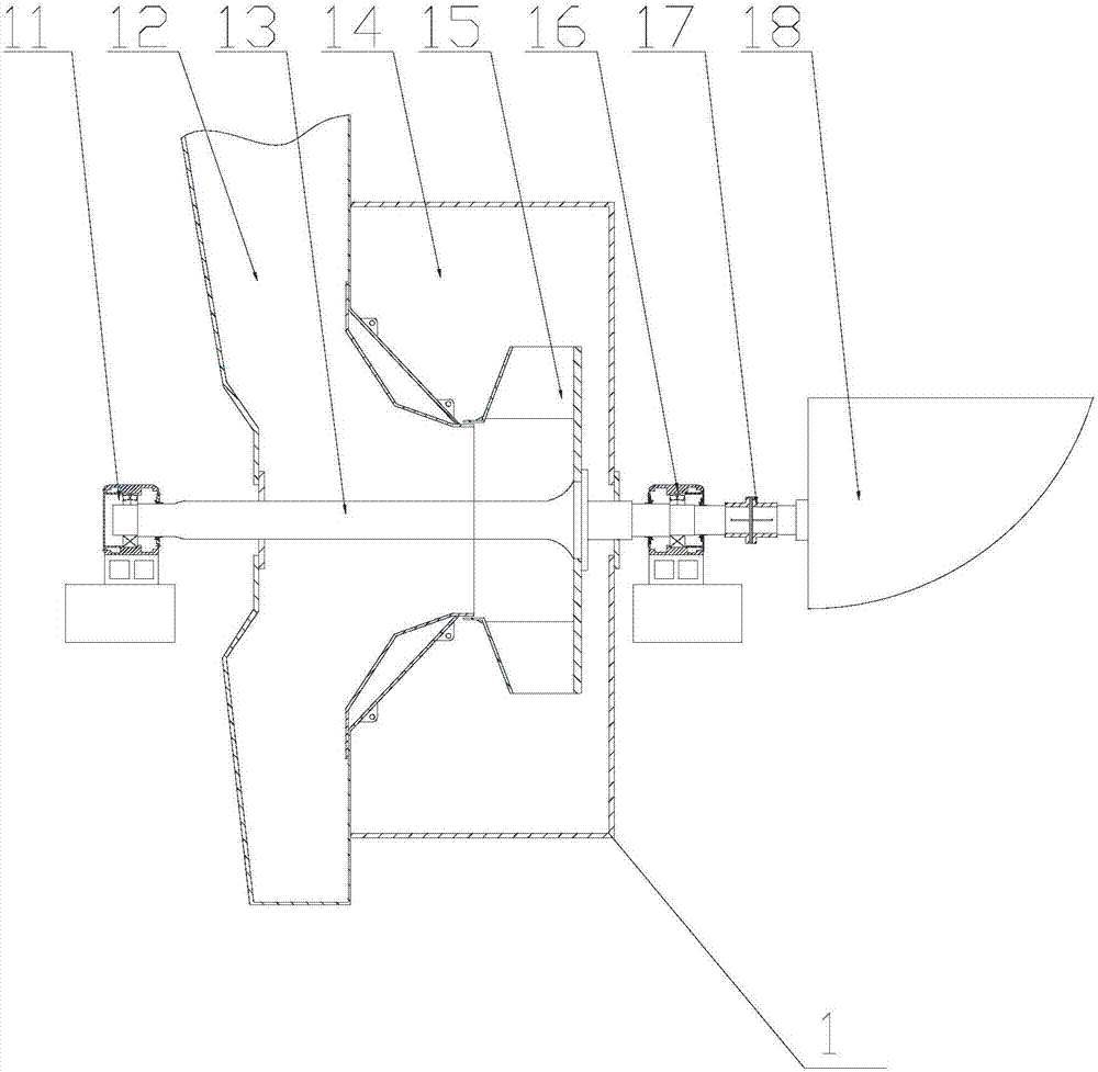
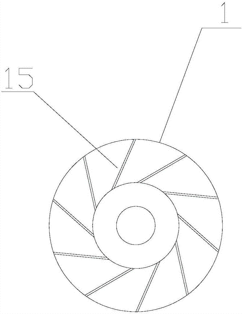
[0034] The present invention provides a large centrifugal fan, the structure of which is as follows: Figures 4 to 8 As shown, it includes a casing 1, the center of the casing 1 is provided with an impeller shaft 13, an impeller 15 is nested on the impeller shaft 13, and a connecting plate 22 is fixed on the inner side wall of the casing 1 on the side close to the impeller 15, and the connecting plate 22 A blowing mechanism 21 is fixed on the upper part. The blowing mechanism 21 is connecte...


PUM


Abstract

The invention provides a large centrifugal blower which comprises a shell. An impeller shaft penetrates through the center of the shell and is embedded into an impeller. A connecting plate is fixedly arranged on the side, close to the impeller, of the inner side wall of the shell. A spraying and blowing mechanism is fixedly arranged on the connecting plate and communicates with a stable-pressure gas storage tank. The spraying and blowing mechanism comprises an annular airflow distributor and a plurality of nozzles uniformly arranged on the circular surface of the annular airflow distributor. Compared with the prior art, the large centrifugal blower has the following beneficial effects that compressed air is sprayed and blown onto blades of the blower, so that the whole impeller of the blower is driven to rotate, then the blower is started after the speed is uniform, and accordingly, a starting load of the blower is reduced; and the annular distributor sprays and blows the impeller of the blower to generate couple, so that stress equilibrium of the impeller of the blower during starting is guaranteed.

Description

technical field [0001] The invention relates to a large centrifugal fan, belonging to the technical field of large dust removal equipment. Background technique [0002] Steel-making dust removal is to collect high-temperature dust generated during steel-making. Among them, the ash is centrally treated, and the clean air is discharged into the atmosphere. Its collection process is as follows figure 1 shown. [0003] The dust removal process of steelmaking mainly uses air as a carrier to collect dust, and then separates the air and dust to achieve dust collection. Moving elbows and roof hoods draw dust into the ducts by airflow. The initial separation and cooling of the flue gas is realized in the mechanical air cooler, and the larger solid particles will be filtered here. Smaller solid particles are accelerated by the booster fan and enter the bag filter through the conveying pipeline. Complete separation of solid particles and air is achieved in the bag filter. Dust e...

Claims


Application Information

Patent Timeline
Patent Type & Authority Applications(China)
IPC IPC(8): F04D25/04F04D25/08
CPCF04D25/045F04D25/08
Inventor 张利杰
Owner BAOSTEEL SPECIAL STEEL CO LTD
Why Eureka
Try Eureka