Thrust chamber of variable working condition liquid-propellant rocket engine

A liquid rocket and engine technology, which is applied in rocket engine devices, machines/engines, mechanical equipment, etc., can solve the problems of high supply pressure in the supply system and the inability to meet the task requirements of a wide range of variable working conditions, and achieve uniform injection Effect

Active Publication Date: 2019-11-12
NORTHWESTERN POLYTECHNICAL UNIV
View PDF7 Cites 4 Cited by
  • Summary
  • Abstract
  • Description
  • Claims
  • Application Information

AI Technical Summary

Problems solved by technology

[0003] At present, the main solution used for the variable working condition liquid rocket engine of the RBCC engine is to use a single nozzle injector with a fixed geometric structure, and to realize the variable working condition by adjusting the pressure drop of the nozzle. Although the structure of this adjustment scheme is simple, the supply system supply too high pressure
Limited by the propellant inlet pressure, its adjustment ratio is about 1 / 3-1 / 2, which cannot meet the mission requirements of a wide range of variable working conditions

Method used


Image

  • Thrust chamber of variable working condition liquid-propellant rocket engine
  • Thrust chamber of variable working condition liquid-propellant rocket engine
  • Thrust chamber of variable working condition liquid-propellant rocket engine

Examples


Embodiment Construction

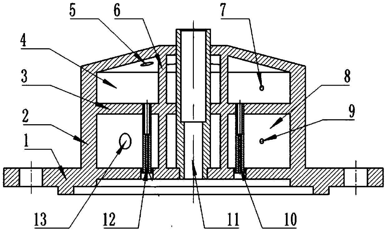
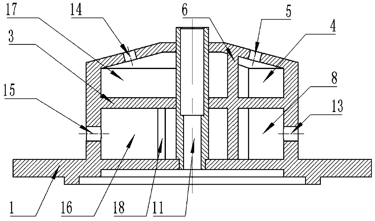
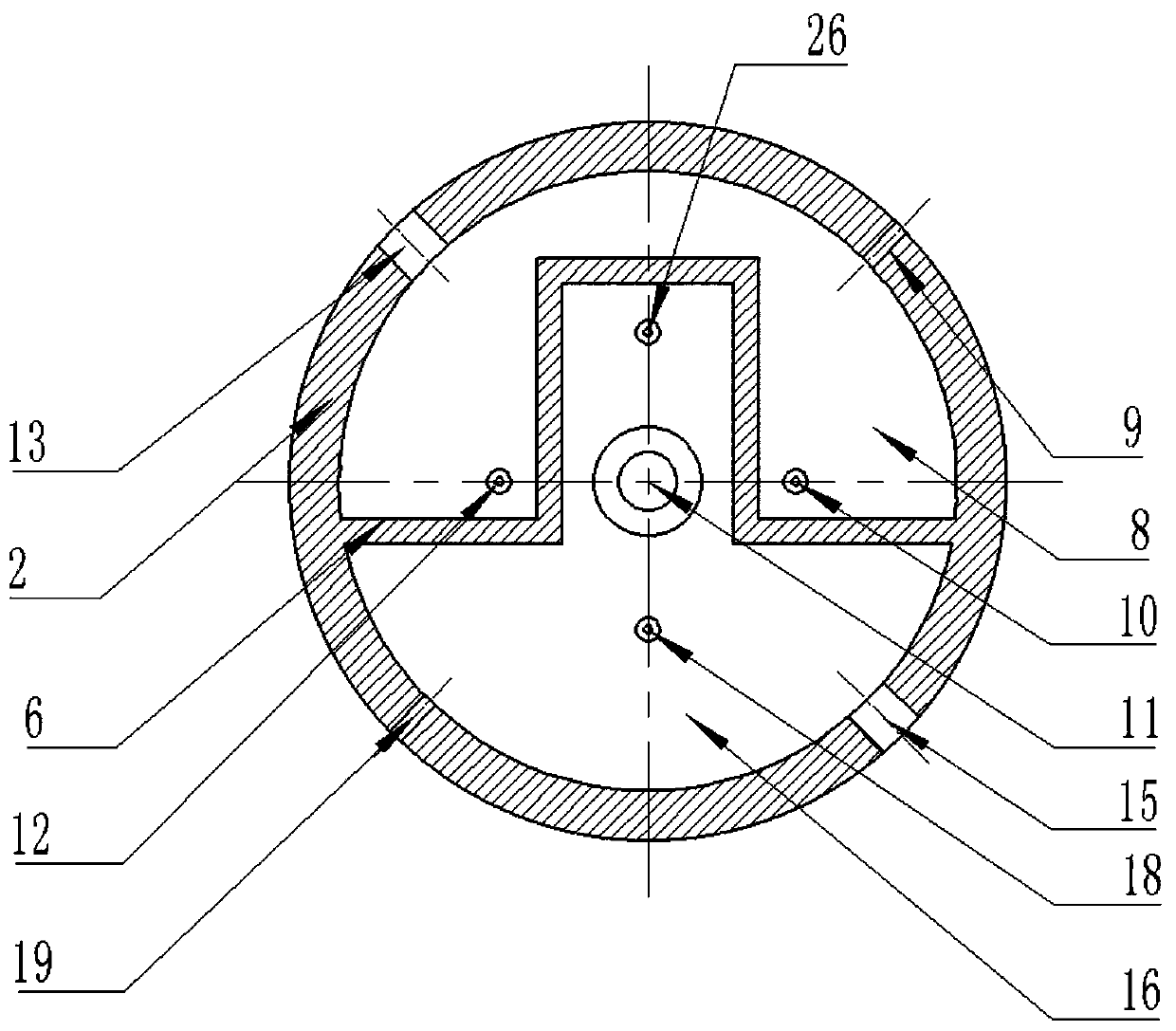
[0023] The present invention is a liquid rocket engine thrust chamber with variable working conditions, such as figure 1 and 2 As shown, it includes: the head body 2, which is a rotary shell structure, the cross section of the rotary shell is circular, and an annular cavity is formed in the shell; the center of the head body 2 is used for axially setting the igniter; the circle An igniter mounting seat 11 is installed in the center of the ring, and the igniter mounting seat 11 is a support. Two groups of gas-liquid outlet holes are opened at the bottom of the rotary housing, and each group is two. The rotary housing includes: a conical housing, with a through hole axially opened at the central axis, and annular cavities with different diameters are formed in the housing; a cylindrical housing, integrally connected with the lower end of the conical housing, and a A through hole is opened in the axial direction, and an annular cavity is formed in the casing. The lower end of ...


PUM


Abstract

The invention discloses a thrust chamber of a variable working condition liquid-propellant rocket engine. The thrust chamber comprises a head body, an upper and lower division plate, and left and right division plates, wherein the head body is of a rotary shell structure; the cross section of the rotary shell is in the shape of a circular ring; an annular cavity is formed in the shell; the centerof the head body is used for axially arranging an igniter; two sets of gas-liquid outlets are formed at the bottom of the rotary shell; each set of gas-liquid outlets comprise two gas-liquid outlets;the upper and lower division plate is horizontally arranged in the annular cavity of the head body, and divides the annular cavity into an upper layer and a lower layer; fuel outlets are formed in theupper and lower division plate and are located at positions corresponding to the gas-liquid outlets; the left and right division plates are vertically arranged in the upper annular cavity and the lower annular cavity; the positions of the left and right division plates correspond; each left and right division plate divides the annular cavity of each layer into two independent cavities; and one set of gas-liquid outlets in the same position and the fuel outlets are located at the bottom of the corresponding rotary shell in one cavity and on the upper and lower division plate. The thrust chamber can realize the wide-range adjustment of flow, and does not cause the excessive pressure in a supply system.

Description

technical field [0001] The invention belongs to the technical field of liquid rocket engine propulsion, and in particular relates to a liquid rocket engine thrust chamber with variable working conditions. Background technique [0002] The working performance of the primary rocket is particularly important to the entire working process of the rocket-based combined cycle (Rocket-based Combined Cycle, RBCC) engine. Further guarantee the stable operation of the RBCC engine. Under variable working conditions, the combustion stability and combustion efficiency of the propellant must be ensured first, so as to further ensure the working stability and efficiency of the engine. The structure of the injector determines the atomization and mixing effect of the propellant. , so designing an injector with good atomization and mixing effects under a wide range of variable working conditions is of great significance to the performance of RBCC engines. [0003] At present, the main soluti...

Claims


Application Information

Patent Timeline
IPC IPC(8): F02K9/62F02K9/58F02K9/52
CPCF02K9/52F02K9/58F02K9/62
Inventor 魏祥庚卞香港赵志新朱韶华李玲玉左有幸秦飞
Owner NORTHWESTERN POLYTECHNICAL UNIV
Why Eureka
Try Eureka