

Camera telescopic adjusting mechanism and wearing device
A telescopic adjustment, camera technology, applied in mechanical equipment, supporting machines, machines/brackets, etc., can solve problems such as easy damage to cameras
- Summary
- Abstract
- Description
- Claims
- Application Information
AI Technical Summary
Problems solved by technology
Method used
Image

Examples
Embodiment Construction
[0023] In order to make the object, technical solution and advantages of the present invention clearer, the present invention will be further described in detail below in conjunction with the accompanying drawings and embodiments. It should be understood that the specific embodiments described here are only used to explain the present invention, not to limit the present invention.
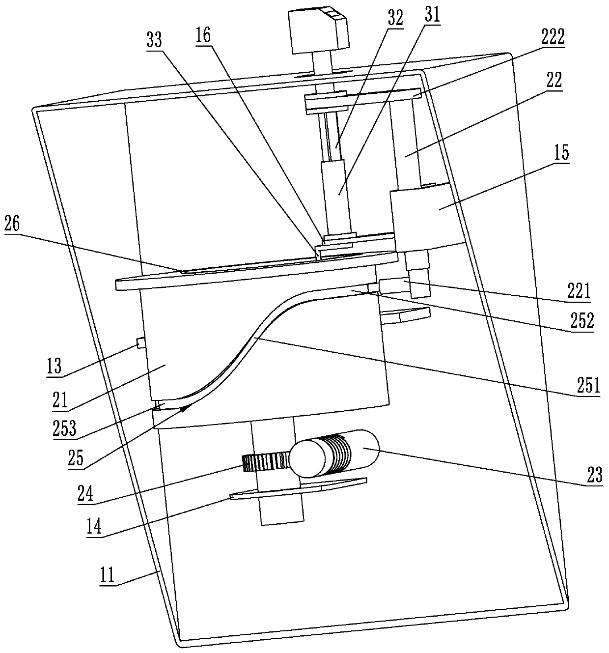
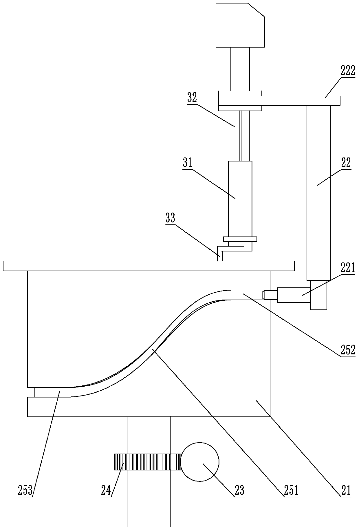
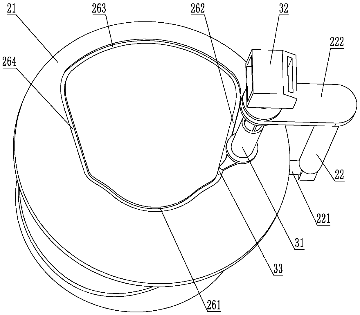
[0024] Figure 1 to Figure 6 It is a structural schematic diagram of the telescopic adjustment mechanism of the camera according to the embodiment of the present invention, wherein, figure 1 A schematic diagram of the three-dimensional structure of the telescopic adjustment mechanism of the camera according to the embodiment of the present invention is shown, figure 2 It shows a front view structural diagram of the transmission mechanism of the telescopic adjustment mechanism of the camera according to the embodiment of the present invention, image 3 A schematic diagram showing the three-dimens...
PUM
 Abstract
Description
Claims
Application Information