Coil winding device

A winding and coiling technology, which is applied in the field of transformers, can solve problems affecting the quality of transformers, insulation damage on the surface of electromagnetic wires, crossing friction of wires, etc., and achieve the effects of increasing friction, ensuring quality, and avoiding left and right movement

Pending Publication Date: 2019-11-12
广州骏发电气设备有限公司
View PDF0 Cites 0 Cited by
  • Summary
  • Abstract
  • Description
  • Claims
  • Application Information

AI Technical Summary

Problems solved by technology

However, when the coil is wound, the wire will move left and right along the coil, and the wire is prone to cross friction, which will cause the surface insulation of the electromagnetic wire to be damaged and affect the quality of the transformer.

Method used


Image

  • Coil winding device
  • Coil winding device
  • Coil winding device

Examples


Embodiment 1

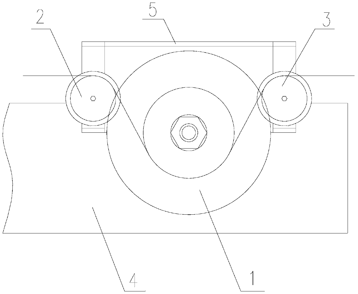
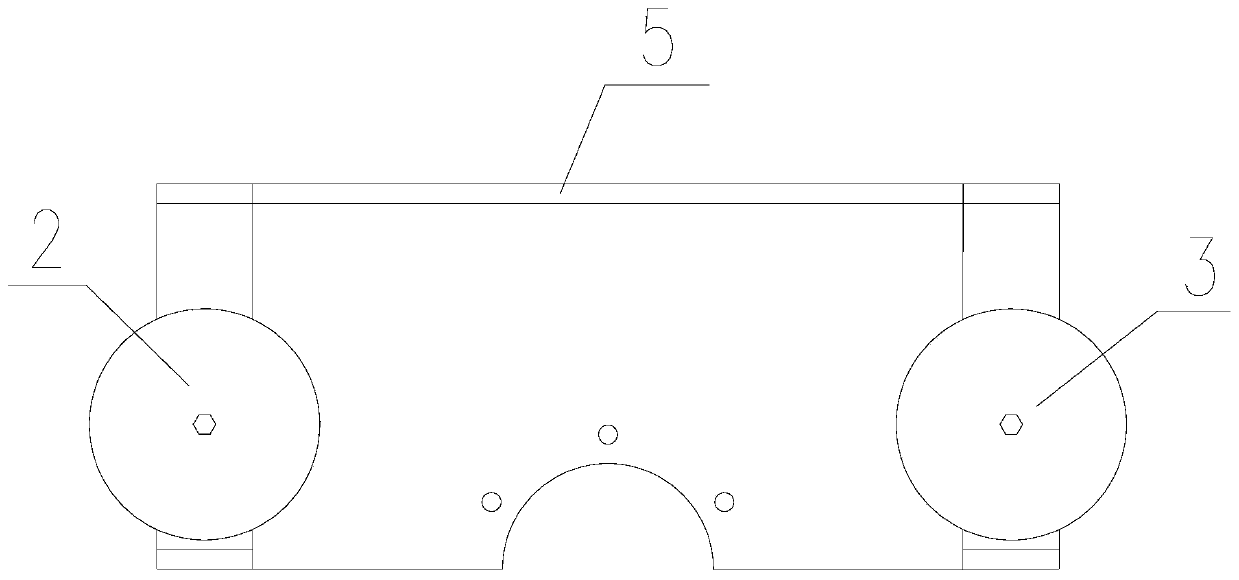
[0023] Such as Figure 1-3 As shown, the coil winding device includes a wire reel 1, a first guide wheel 2 and a second guide wheel 3, and the first guide wheel 2 and the second guide wheel 3 are respectively arranged on both sides of the wire reel 1. Preferably, the wire reel 1, the first guide wheel 2 and the second guide wheel 3 are distributed in the shape of "pin".

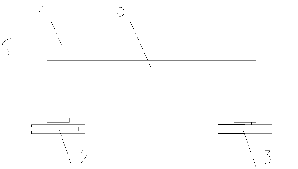
[0024] The wire reel 1 is installed on the pay-off frame 4 , the first guide wheel 2 and the second guide wheel 3 are installed on the base 5 , and the base 5 is detachably connected with the pay-off frame 4 . By connecting the base 5 with the pay-off frame 4, the first guide wheel 2 and the second guide wheel 3 can be fixed on both sides of the wire reel 1 conveniently and quickly.

[0025] The device also includes devices such as a winding machine and a pay-off reel. Firstly, the wire reel 1 is installed and fixed on the pay-off frame 4, and then the base 5 is fixedly connected with the pay-off frame 4, s...

Embodiment 2

[0027] Such as Figure 1-3 As shown, the coil winding device includes a wire reel 1, a first guide wheel 2 and a second guide wheel 3, and the first guide wheel 2 and the second guide wheel 3 are respectively arranged on both sides of the wire reel 1. Preferably, the wire reel 1, the first guide wheel 2 and the second guide wheel 3 are distributed in the shape of "pin".

[0028] The wire reel 1 is installed on the pay-off frame 4 , the first guide wheel 2 and the second guide wheel 3 are installed on the base 5 , and the base 5 is detachably connected with the pay-off frame 4 . By connecting the base 5 with the pay-off frame 4, the first guide wheel 2 and the second guide wheel 3 can be fixed on both sides of the wire reel 1 conveniently and quickly.

[0029] The device also includes devices such as a winding machine and a pay-off reel. Firstly, the wire reel 1 is installed and fixed on the pay-off frame 4, and then the base 5 is fixedly connected with the pay-off frame 4, s...

Embodiment 3

[0032] Such as Figure 1-3 As shown, the coil winding device includes a wire reel 1, a first guide wheel 2 and a second guide wheel 3, and the first guide wheel 2 and the second guide wheel 3 are respectively arranged on both sides of the wire reel 1. Preferably, the wire reel 1, the first guide wheel 2 and the second guide wheel 3 are distributed in the shape of "pin".

[0033] The wire reel 1 is installed on the pay-off frame 4 , the first guide wheel 2 and the second guide wheel 3 are installed on the base 5 , and the base 5 is detachably connected with the pay-off frame 4 . By connecting the base 5 with the pay-off frame 4, the first guide wheel 2 and the second guide wheel 3 can be fixed on both sides of the wire reel 1 conveniently and quickly.

[0034] The device also includes devices such as a winding machine and a pay-off reel. Firstly, the wire reel 1 is installed and fixed on the pay-off frame 4, and then the base 5 is fixedly connected with the pay-off frame 4, s...


PUM


Abstract

The invention belongs to the technical field of transformers, and discloses a coil winding device. The device comprises a wire coil (1), a first wire guide wheel (2) and a second wire guide wheel (3),wherein the first wire guide wheel (2) and the second wire guide wheel (3) are respectively arranged at the two sides of the wire coil (1), and the wire coil (1) is installed on a pay-off rack (4); the first wire guide wheel (2) and the second wire guide wheel (3) are detachably connected with the pay-off rack (4). Through the arrangement of the first wire guide wheel and the second wire guide wheel, a friction force is increased, a tensioning force needed by coil winding is achieved, and meanwhile, the left-right movement and cross friction of the electromagnetic wire are effectively avoided, and the quality of the electromagnetic wire is guaranteed.

Description

technical field [0001] The invention belongs to the technical field of transformers, in particular to a coil winding device. Background technique [0002] When winding the coil, it is necessary to ensure the winding speed of the coil and the tension of the wire. If the coil is wound too fast, the tension will increase, which will easily cause the wire to become smaller and elongated; if the coil is wound too slowly, the production efficiency will be low. Since the surface of the magnet wire is relatively smooth, the speed of unwinding the magnet wire is fast. When the magnet wire is wound into a coil, it is necessary to increase the friction by setting up the coil and let the magnet wire wind the coil for one turn to achieve the tension required for coil winding. Tight force. However, when the coil is wound, the wire will move left and right along the coil, and the wire is prone to cross friction, which will cause the surface insulation of the electromagnetic wire to be da...

Claims


Application Information

Patent Timeline
Patent Type & Authority Applications(China)
IPC IPC(8): H01F41/06H01F41/094H01F41/096
CPCH01F41/06H01F41/094H01F41/096
Inventor 黄登威廖江乐颜泽华陆燕君
Owner 广州骏发电气设备有限公司
Why Eureka
Try Eureka