Intelligent cupping machine

A cupping machine and intelligent technology, applied in the field of medical devices, can solve the problems of inability to accurately guarantee the treatment effect, treatment time, different negative pressure and temperature and humidity in the tank, and great differences in safety and effectiveness.

Inactive Publication Date: 2019-11-15
王作涪 +2
View PDF8 Cites 1 Cited by
  • Summary
  • Abstract
  • Description
  • Claims
  • Application Information

AI Technical Summary

Problems solved by technology

[0002] Vacuum cupping devices and cupping pots commonly used in the market currently simply use negative pressure to promote local blood circulation in the human body. Many existing cupping pots use open flames to burn the air in the pot to generate negative pressure for treatment. There is a great potential safety hazard in the way of open flames
The vacuum cupping device only simply extracts the air in the tank, and the above two cupping devices cannot monitor detailed information such as pressure, temperature and humidity in the tank.
In the traditional cupping treatment process, the same patient will have different treatment time, negative pressure inside the tank, temperature and humidity due to different operators and users.
At the same time, for individuals with different tolerance, if the negative pressure is too high, it will cause skin damage, and if the negative pressure is not enough, the effectiveness of the treatment will not be ideal.
Even if it is the same operating user, it cannot accurately guarantee that each treatment will achieve a perfect therapeutic effect
Therefore, in clinical use, it is mainly used empirically, and the safety and effectiveness of different operators vary greatly, which limits the scientific use and widespread promotion of this treatment method to a certain extent. At the same time, the universal cupping device function It is also too single, which also leads to a single treatment effect

Method used


Image

  • Intelligent cupping machine

Examples


Embodiment Construction

[0030] The specific embodiments of the present invention will be further described in detail below with reference to the accompanying drawings.

[0031] In order to specifically understand the technical solutions provided by the present invention, the technical solutions of the present invention will be described and illustrated in detail in the following embodiments. Obviously, the embodiments provided by the present invention are not limited to the specific details familiar to those skilled in the art. The preferred embodiments of the present invention are described in detail below, and in addition to these descriptions, the present invention may have other embodiments.

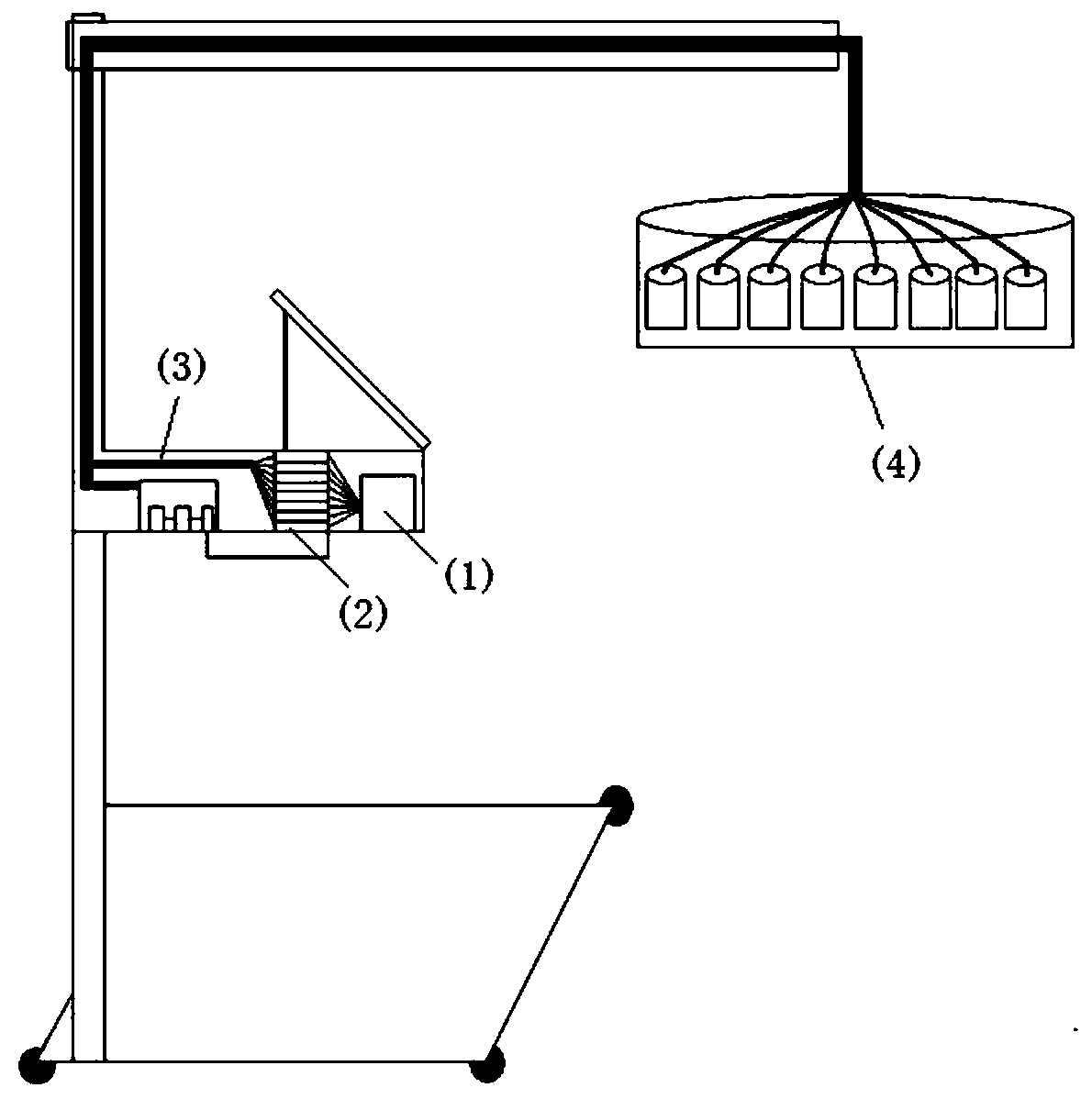
[0032] like figure 1 As shown, the specific embodiment of the present invention relates to an intelligent cupping machine, comprising: a cupping machine frame, several tanks (4) and air valves (2) fixed on the frame, an air pump (1), an air duct, a main engine (3), a display and an input control terminal,...


PUM


Abstract

The invention discloses an intelligent cupping machine. The machine comprises a cupping machine frame, a plurality of cup bodies and air valves which are fixed on the machine frame, an air pump, an air duct, a host, a display, an input control terminal, and a physiotherapy device and a sensor which are arranged in each cup body; the top end of each cup body is provided with an air extraction port;both the air exhaust port of each cup body and the air pump are connected to an air guide pipe; an air duct connected to the air extraction port of each cup body communicates with the input end of each air valve, and an air duct connected to each air pump communicates with the output end of each air valve; the display and the input control terminal are connected to the host; and the host communicating with the cloud big data platform through the network is connected to the sensor, the physiotherapy device and the air valves respectively. According to the scheme, the temperature, humidity andpressure in the cup bodies of the intelligent cupping machine can be monitored and controlled in real time; and according to detailed information such as the pressure, the temperature and the humiditywhich are acquired in real time in the cup bodies, and according to the difference of the tolerance degree and the physical condition of individual patients, different treatment schemes are implemented, so that the patient experience degree is improved under the condition of ensuring the treatment effect.

Description

technical field [0001] The invention relates to a medical apparatus, in particular to an intelligent cupping machine. Background technique [0002] At present, the vacuum cupping devices and cupping cups commonly used in the market usually simply use negative pressure to promote local blood circulation in the human body. Many existing cupping cups use an open flame to burn the air in the tank to generate negative pressure for treatment. This kind of use There is a great safety hazard in the way of open flame. The vacuum cupping device simply extracts the air in the tank, and neither of the above two cupping devices can monitor the detailed information such as the pressure, temperature and humidity in the tank. In the traditional cupping treatment process, the treatment time, negative pressure in the cup, temperature and humidity will be different for the same patient due to different operators and users. At the same time, for individuals with different tolerances, if the n...

Claims


Application Information

Patent Timeline
Patent Type & Authority Applications(China)
IPC IPC(8): A61M1/08A61H9/00A61N5/06A61N5/067
CPCA61M1/0003A61H9/0057A61H2201/10A61H2201/5071A61M1/08A61M2205/3331A61M2205/3368A61N5/0613A61N5/067
Inventor 王作涪吴运德李志新
Owner 王作涪
Why Eureka
Try Eureka