
Injection mold with step-by-step demolding structure

An injection mold and mold release technology, which is applied in the field of injection molds with a step-by-step mold release structure, can solve the problems of mold complexity, reduced reliability and stability, and inability to release the mold normally, and achieves good reliability and stability. , the effect of simple structure

Active Publication Date: 2019-11-15
NINGBO BOCHAO MOLD
View PDF5 Cites 2 Cited by
  • Summary
  • Abstract
  • Description
  • Claims
  • Application Information

AI Technical Summary

Problems solved by technology

Since the direction of the supporting column is just opposite to the opening direction of the upper mold, if the slider and the inclined guide column of the conventional injection mold are used to demould in two steps, the normal demoulding will not be possible.
If demoulding must be completed, many parts must be added to achieve it, which will cause the complexity of the mold, thereby reducing reliability and stability

Method used


Image

  • Injection mold with step-by-step demolding structure
  • Injection mold with step-by-step demolding structure
  • Injection mold with step-by-step demolding structure

Examples


Embodiment Construction

[0024] The present invention will be further described below in conjunction with the accompanying drawings.

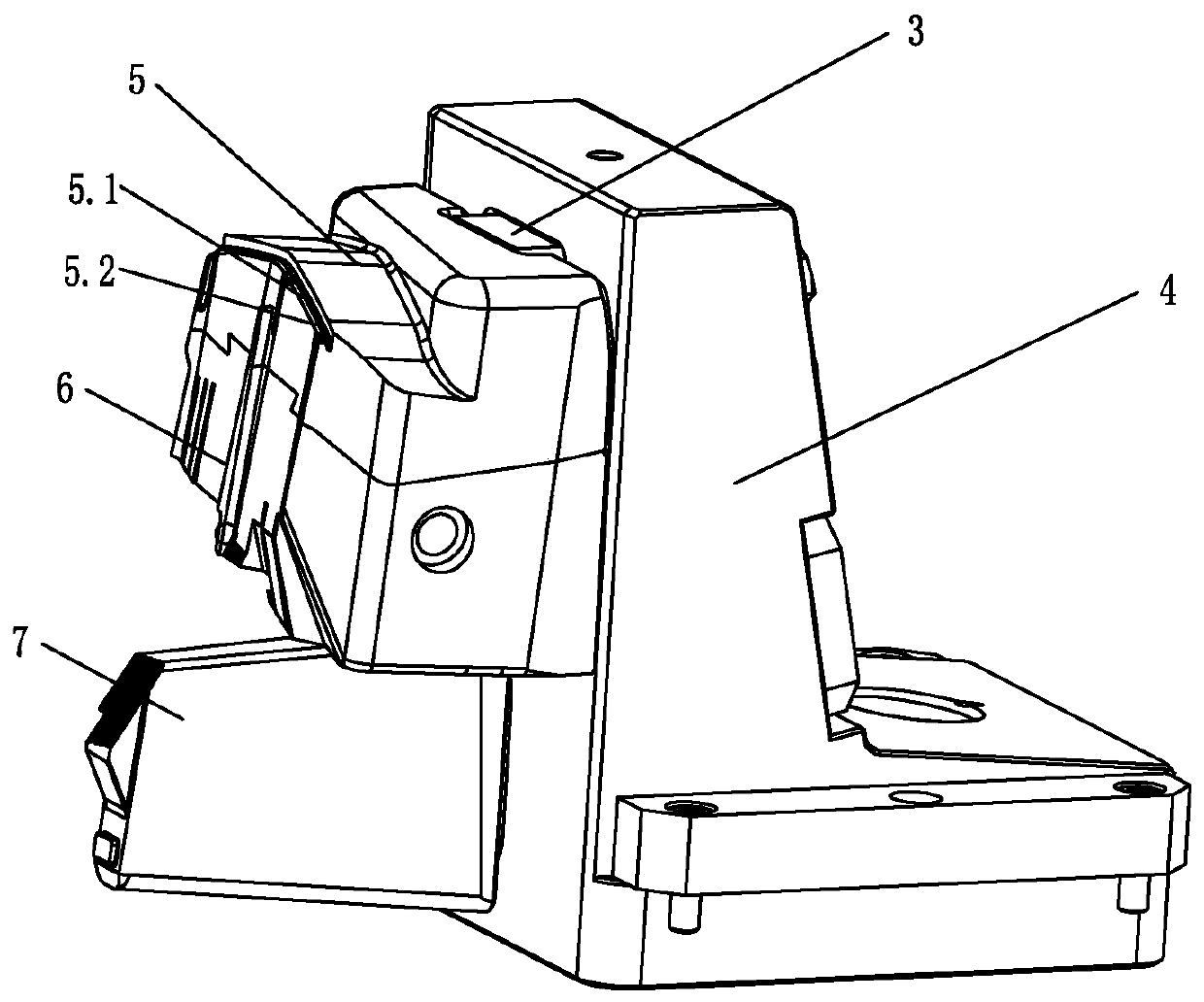
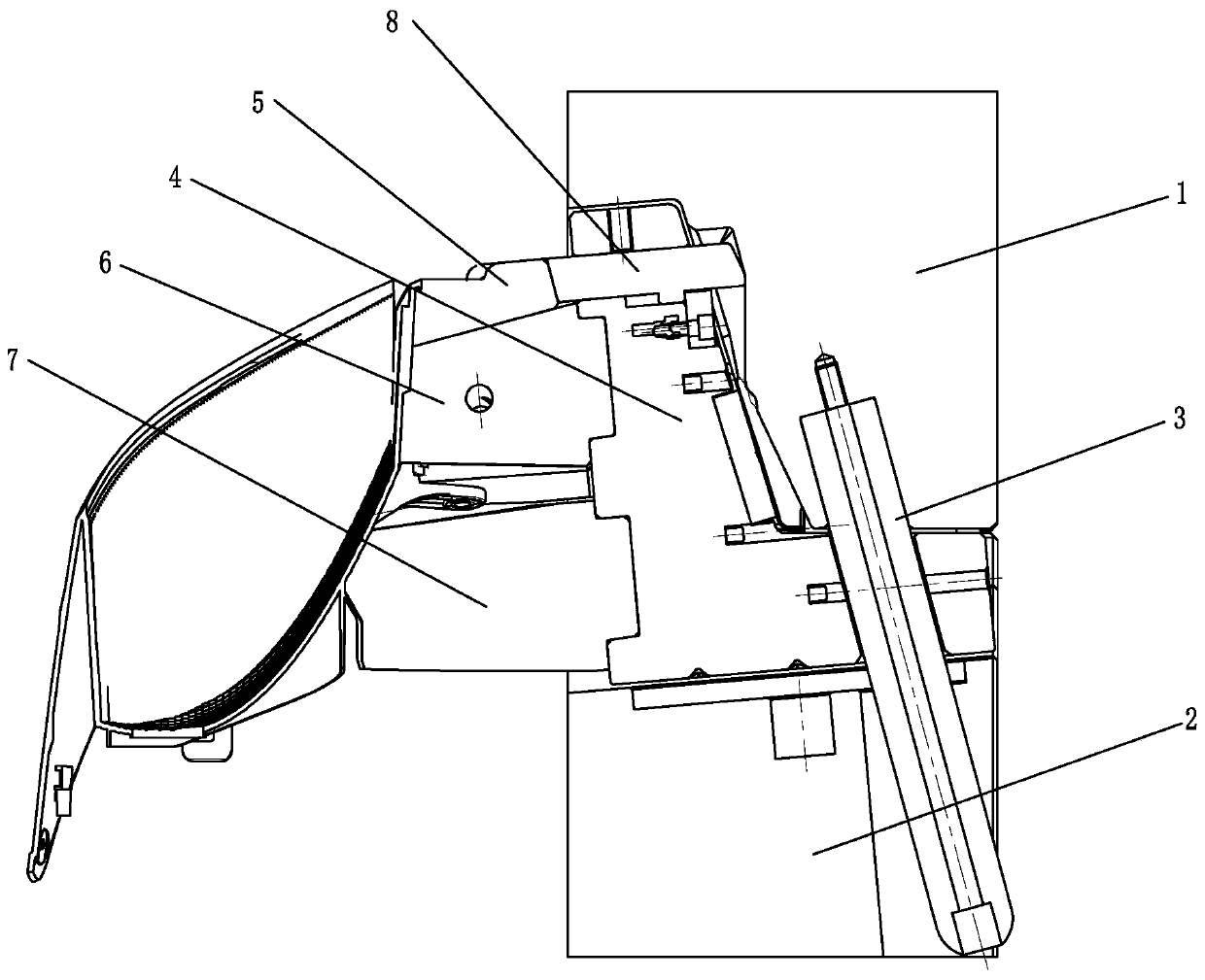
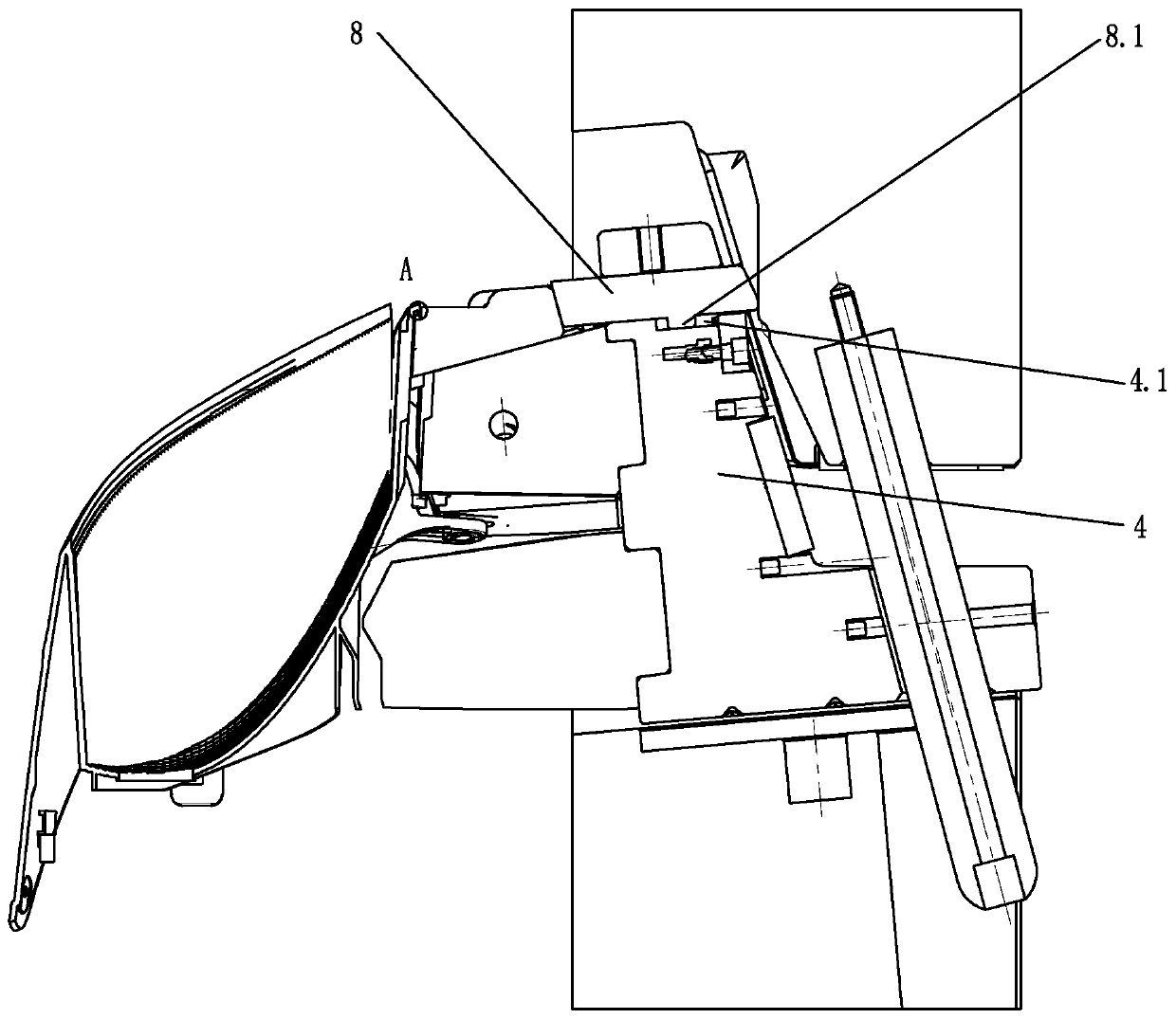
[0025] like Figure 1-5 As shown, the injection mold with the step-by-step demolding structure of the present invention includes an upper mold 1 and a lower mold 2, the upper mold 1 is provided with an inclined guide column 3, and the lower mold 2 is provided with a slider 4, The first insert 5 , the second insert 6 , and the third insert 7 , the sliding block 4 is slidably connected with the lower mold 2 and the connection is the first sliding surface, and the bottom surface of the sliding block 4 is connected to the lower mold 2 . The first sliding surfaces between the top surfaces are inclined at 5-8 degrees, and the side close to the product 101 is lower than the side away from the product 101 .

[0026] The first insert 5 , the second insert 6 , and the third insert 7 are located on the side of the slide 4 from top to bottom and serve as a part of the cavity of t...


PUM


Abstract

The invention discloses an injection mold with a step-by-step demolding structure. The injection mold with the step-by-step demolding structure comprises an upper mold (1) and a lower mold (2), wherein the upper mold (1) is provided with an inclined guide column (3), the lower mold (2) is provided with a sliding block (4), a first insert (5), a second insert (6) and a third insert (7); the openingmold has a two-step state: the first step state of the opening mold, the first insert (5) faces down along a sliding surface, a raised line (5.2) moves down to the bottom of a support column (102) ofa product (101); and the second step state of the opening mold, the upper mold (1) and the inclined guide column (3) raise upward by a distance D2 and are separated from the sliding block (4), the sliding block (4) drives the first insert (5), the second insert (6), the third insert (7) and a top block (8) to be away from the shaped product (101). The mold adopts two-step demolding, and has a simple structure, can achieve normal demolding, and has good reliability and stability.

Description

technical field [0001] The invention relates to the technical field of injection molds, in particular to an injection mold with a step-by-step demolding structure. Background technique [0002] At present, there is a bracket for installing a fog lamp on an automobile, and a support column is arranged on the inner side of the edge of the bracket, and the support column extends along the center of the bracket. Since the orientation of the support column is just opposite to the opening direction of the upper mold, if the sliding block and the inclined guide column of the conventional injection mold are used to demold in two steps, it cannot be demolded normally. If demolding must be completed, many parts must be added to achieve it, which will complicate the mold and reduce reliability and stability. SUMMARY OF THE INVENTION [0003] The technical problem to be solved by the present invention is to provide an injection mold that adopts two-step demoulding, has a simple struc...

Claims


Application Information

Patent Timeline
IPC IPC(8): B29C45/40
CPCB29C45/4005
Inventor 施涛叶晓莹徐茂盛叶海国
Owner NINGBO BOCHAO MOLD
Learn More