
Stripping device

A stripping device and component technology, applied in the direction of layered products, lamination, etc., can solve the problems of stripping failure of the stripping device, achieve the effect of avoiding stripping failure, improving production efficiency and product yield

Active Publication Date: 2019-11-15
SHENZHEN CHINA STAR OPTOELECTRONICS SEMICON DISPLAY TECH CO LTD
View PDF5 Cites 1 Cited by
  • Summary
  • Abstract
  • Description
  • Claims
  • Application Information

AI Technical Summary

Problems solved by technology

[0004] The application provides a peeling device to solve the technical problem of peeling failure of the existing peeling device

Method used


Image

  • Stripping device
  • Stripping device
  • Stripping device

Examples


Embodiment Construction

[0044] The following descriptions of the various embodiments refer to the accompanying drawings to illustrate specific embodiments that the present application can be used to implement. The directional terms mentioned in this application, such as [top], [bottom], [front], [back], [left], [right], [inside], [outside], [side], etc., are for reference only The orientation of the attached schema. Therefore, the directional terms used are used to illustrate and understand the application, but not to limit the application. In the figures, structurally similar elements are denoted by the same reference numerals.

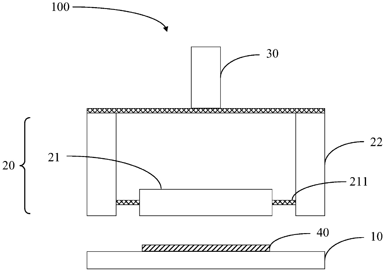
[0045] see figure 1 , figure 1 It is a structural diagram of the peeling device of the present application.

[0046] The stripping device 100 includes a base 10, a stripping assembly 20, a driving assembly 30, a support arm (not shown) and a controller (not shown).

[0047] The base 10 is used to carry and fix the member 40 to be stripped.

[0048] In this embodiment,...


PUM


Abstract

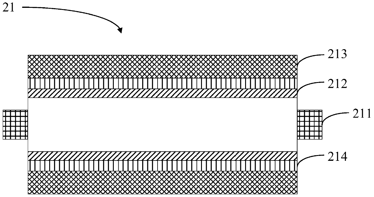
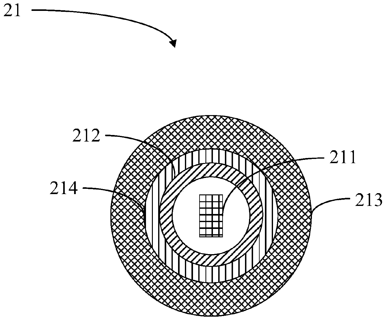
The present invention provides a stripping device. The stripping device comprises: a base for fixing a member to be stripped; a stripping assembly comprising a drum, wherein the drum comprises supportrods, a pressure gauge, and measuring layers located on the outer rings of the support rods; and a driving assembly used for driving the stripping assembly to move towards the member to be stripped.A pressure sensor is arranged in the stripping assembly to obtain the pressure applied to the member to be stripped by the stripping assembly in real time, and different pressures are applied to polarizing plates with different thicknesses in order to avoid the technical problems of stripping failure of a release film and folding damages of the polarizing plates, so the production efficiency and the product yield are increased.

Description

technical field [0001] The present application relates to the display field, in particular to a stripping device. Background technique [0002] In the field of display panels, the polarizer needs to remove the release film on the surface of the polarizer before attaching the polarizer. [0003] In the prior art, the roller of the peeling assembly is in contact with the release film mainly by controlling the height of the peeling assembly, and the release film is rolled up and removed by utilizing the stickiness of the roller. Since the peeling component in this peeling method contacts the release film by descending a fixed height, the contact state between the roller and the polarizer is different for polarizers of different thicknesses, which may cause peeling failure of the release film or breakage of the polarizer And other technical issues, affecting production efficiency and product yield. Contents of the invention [0004] The application provides a peeling device ...

Claims


Application Information

Patent Timeline
Patent Type & Authority Applications(China)
IPC IPC(8): B32B43/00
CPCB32B43/006
Inventor 董德世
Owner SHENZHEN CHINA STAR OPTOELECTRONICS SEMICON DISPLAY TECH CO LTD
Learn More