Label peeling mechanism for continuous label strip, and label printer apparatus using the mechanism

a technology of peeling mechanism and label, which is applied in the directions of printing, transportation and packaging, packaging, etc., can solve the problems of high labor intensity, high labor intensity, and high labor intensity, and achieve the effect of reducing labor intensity, reducing manufacturing costs, and reducing the number of construction elements

Active Publication Date: 2006-10-17
SEIKO INSTR INC
View PDF13 Cites 14 Cited by
  • Summary
  • Abstract
  • Description
  • Claims
  • Application Information

AI Technical Summary

Benefits of technology

[0022]The present invention has been made in order to solve the problems described above and is directed to a label peeling mechanism for a continuous label strip which is capable of preventing peeling failure from occurring by suppressing slack in a label sheet, and to a label printer apparatus using the label peeling mechanism.
[0023]According to an aspect of the present invention, there is provided a label peeling mechanism for a continuous label strip, by which a continuous label strip (label sheet Y) obtained by provisionally attaching multiple adhesive label pieces (labels L) to the front surface of a sheet-shaped backing strip (D) at predetermined intervals and winding the backing strip with the label pieces to a roll shape is conveyed and the label pieces are peeled and separated from the backing strip, the label peeling mechanism including: a first conveying unit (platen roller 10, for instance) that conveys the continuous label strip in a first direction (S1 direction) in which the label pieces are continuously arranged; a label peeling member (peeling pin 30, for instance) that is disposed along the first direction so as to be spaced from the first conveying unit by a predetermined distance, is abutted against the underside of the backing strip of the continuous label strip conveyed by the first conveying unit, and peels the label pieces from the backing strip; a second conveying unit (platen roller 10 and peeling roller 20, for instance) that pulls the sheet-shaped backing strip, from which the label pieces have been peeled, in a second direction (S2 direction) that is opposite to the first direction from the label peeling member; and a slack preventing member (40) disposed to oppose the front surface of the continuous label strip between the first conveying unit and the label peeling member and suppresses slack where the continuous label strip floats up to the front surface side.
[0024]With this construction, it becomes possible to suppress the occurrence of a phenomenon where the continuous label strip floats up to the front surface side between the first conveying unit and the label peeling member and to avoid a phenomenon where printed label pieces are spaced from the peripheral surface of the label peeling member and there is reduced an angle at which the continuous label strip makes a U-turn around the label peeling member. As a result, it becomes possible to prevent the occurrence of peeling failure where the label pieces are not peeled by the peripheral surface of the label peeling member and are conveyed along with the backing strip. Also, unlike the conventional case, it is not required to provide a tension mechanism for preventing the slack in the continuous label strip from occurring, which simplifies the construction and makes it possible to reduce the manufacturing cost.

Problems solved by technology

If printed labels are peeled one by one by manual work, this consumes much time and effort, and there occurs an inefficiency problem.
In particular, in the case of labels for commercial use, it is required to peel many labels in a short period of time, so that if this peeling operation is manually conducted, the inefficiency problem becomes prominent.
Consequently, there occurs a problem that the labels L are not peeled by the peripheral surface of the peeling pin 30 and are conveyed along with the backing strip D in the S2 direction.
With this construction, the peeling roller 20 is rotated at all times in the direction of an arrow K1 shown in FIG. 5 and tension is applied to the label sheet Y. In this case, however, there occurs a problem that the construction becomes complicated and the manufacturing cost is increased.

Method used


Image

  • Label peeling mechanism for continuous label strip, and label printer apparatus using the mechanism
  • Label peeling mechanism for continuous label strip, and label printer apparatus using the mechanism
  • Label peeling mechanism for continuous label strip, and label printer apparatus using the mechanism

Examples


Embodiment Construction

[0040]A preferred embodiment of the present invention will now be described with reference to the accompanying drawings.

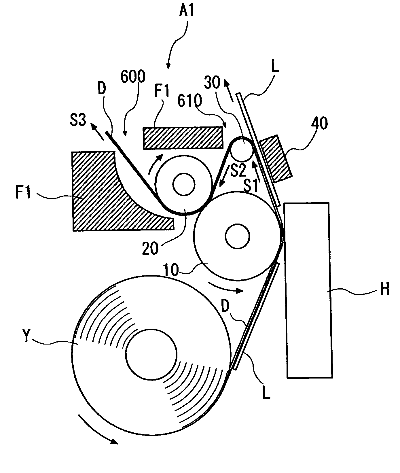
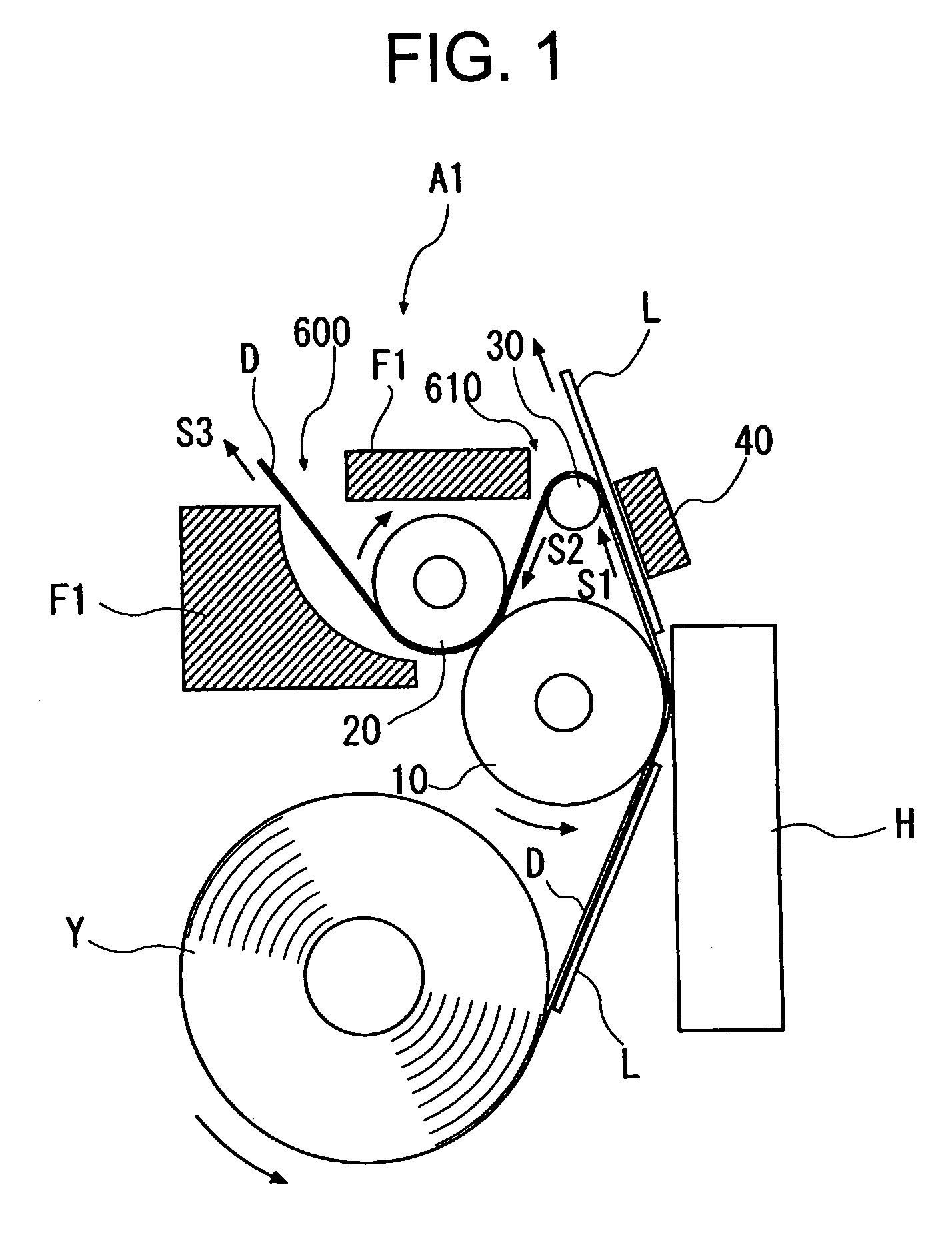
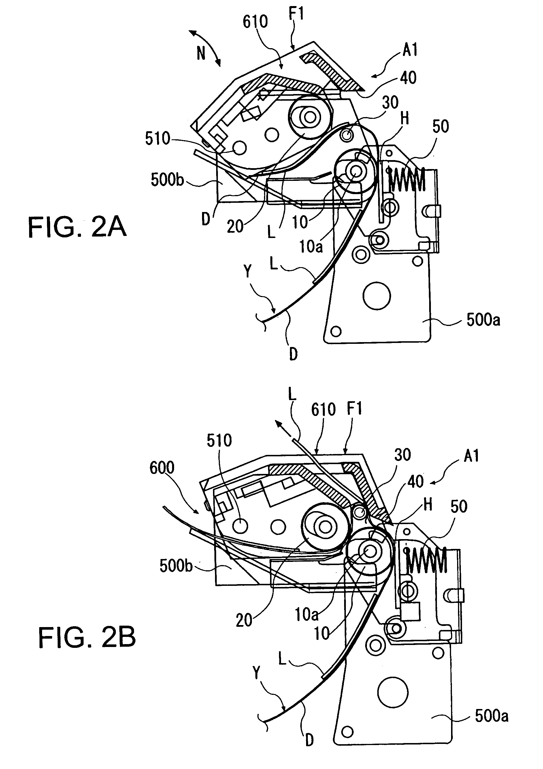
[0041]FIG. 1 is a construction drawing showing an outline of a label printer apparatus according to the present invention, FIGS. 2A and 2B are each a side view showing the main part of the embodiment of the label printer apparatus, FIGS. 3A and 3B are each a perspective view thereof, and FIGS. 4A and 4B are each a side view showing the whole of the label printer apparatus according to the embodiment.

[0042]In FIG. 1, a roll-shaped label sheet Y obtained by provisionally attaching multiple adhesive backed labels L to the front surface of a sheetshaped backing member or strip D at predetermined intervals and coiling or winding the backing strip D with the labels L into a roll is contained in a label printer A1.

[0043]It should be noted here that a printable surface made of a thermal coloring layer is formed on the front surface of each label L and is subjected to prede...


PUM

PropertyMeasurementUnit
distanceaaaaaaaaaa
lengthaaaaaaaaaa
widthaaaaaaaaaa

Abstract

A label peeling mechanism has a peeling member for peeling adhesive backed labels from a backing member of a continuous label strip. A conveying unit conveys the continuous label strip to the peeling member. A discharge frame has a discharge opening for discharging the adhesive backed labels peeled by the peeling member from the backing member of the continuous label strip. A slack preventing member integral with the discharge frame suppresses slack of the continuous label strip as the adhesive backed labels are peeled by the peeling member from the backing member of the continuous label strip.

Description

BACKGROUND OF THE INVENTION[0001]1. Field of the Invention[0002]The present invention relates to a label peeling mechanism for a continuous label strip and to a label printer apparatus using the label peeling mechanism. More specifically, the present invention relates to a label peeling mechanism by which a continuous label strip obtained by provisionally attaching multiple adhesive label pieces to the front surface of a sheet-shaped backing strip and winding the backing strip with the label pieces to a roll shape is conveyed, and the label pieces are peeled and separated from the backing strip at a predetermined position. In particular, the present invention relates to a technique with which it is possible to suppress slack in the conveyed continuous label strip.[0003]2. Description of the Related Art[0004]Conventionally, there has been used a label printer apparatus that uses a continuous label strip (hereinafter referred to as the “label sheet”) obtained by provisionally attachin...

Claims


Application Information

Patent Timeline
Patent Type & Authority Patents(United States)
IPC IPC(8): B32B38/10B41J2/32B41J3/407B41J3/44B65C9/00B65C9/18B65C9/46B65H41/00
CPCB41J3/4075B41J3/44B65C9/0006B65C9/1865B65C2009/0009Y10T156/1168Y10T156/1179Y10T156/1705Y10T156/1195Y10T156/1994Y10T156/1978Y10T156/17Y10T156/171
Inventor ITO, AKIHIKO
Owner SEIKO INSTR INC
Why Eureka
Try Eureka