Spindle drive for the motorized adjustment of an adjustment element of a motor vehicle

a technology for motor vehicles and spindle drives, which is applied in the direction of wing accessories, mechanical equipment, gearing, etc., can solve the problems of considerable additional costs, considerable risk of injury to users, and insufficient 5000 n to prevent the spindle drive from violently falling apart, and achieves high reproducibility of fracture behaviour.

Inactive Publication Date: 2012-02-02
BROSE SCHLIESSSYSTEME GMBH & CO KG
View PDF24 Cites 7 Cited by
  • Summary
  • Abstract
  • Description
  • Claims
  • Application Information

AI Technical Summary

Benefits of technology

[0026]In this case it is essential that a coupling means has a guide pin which is received in a guide sleeve of the associated drive portion and which has a weakening for implementing the predetermined rupture point. In particular, the arrangem

Problems solved by technology

In some cases, even the aforementioned 5000 N are not sufficient in order to prevent the spindle drive from violently falling apart.
The resulting complete relaxation of the spring arrangement also takes place abruptly, as a result of the extreme pretensioning, an

Method used


Image

  • Spindle drive for the motorized adjustment of an adjustment element of a motor vehicle
  • Spindle drive for the motorized adjustment of an adjustment element of a motor vehicle
  • Spindle drive for the motorized adjustment of an adjustment element of a motor vehicle

Examples


Embodiment Construction

[0030]The proposed spindle drive 1 may be used for all possible adjustment elements of a motor vehicle. Examples of this have been provided in the introductory part of the description.

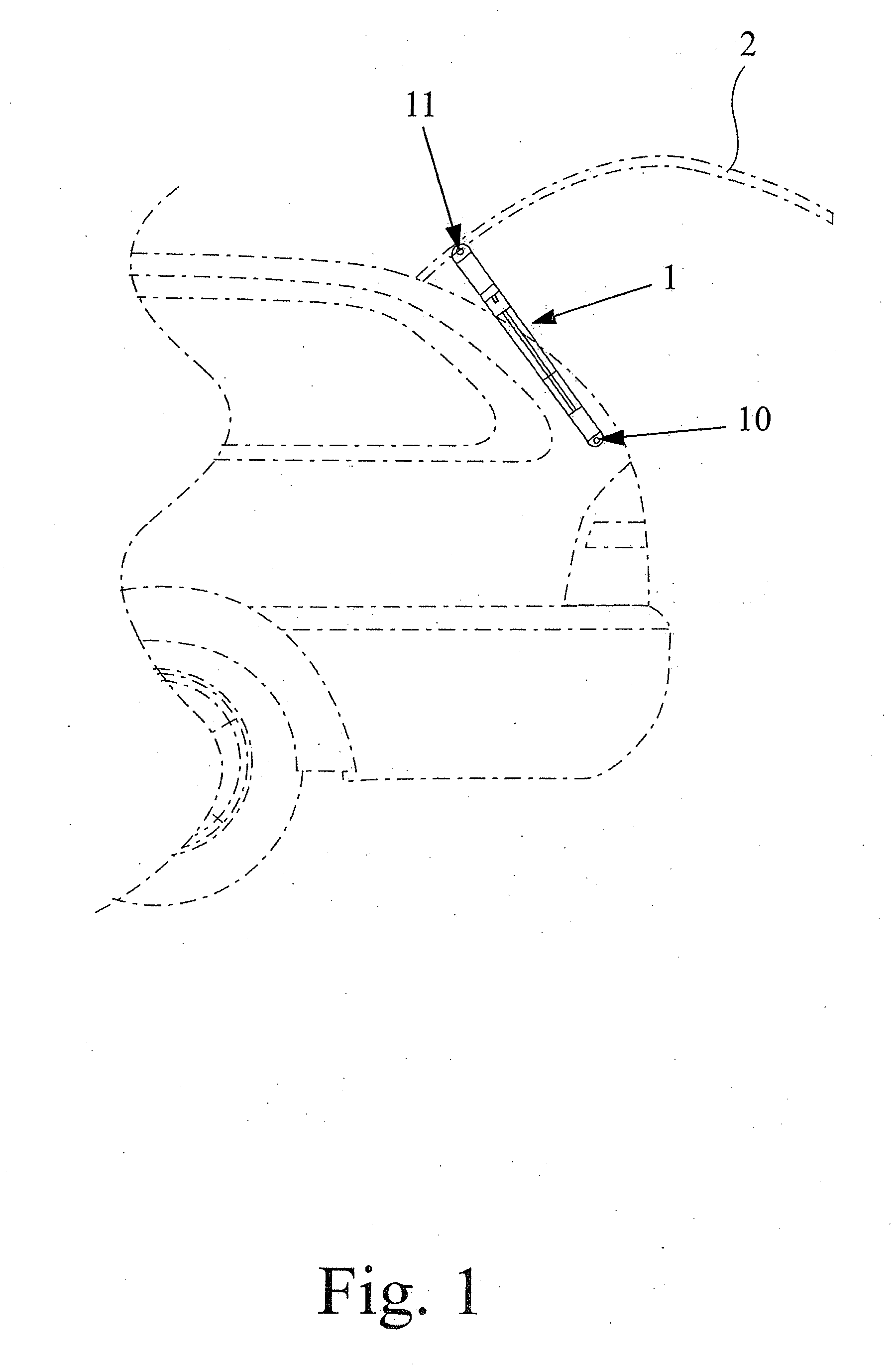
[0031]The spindle drive 1 is described hereinafter exclusively in connection with the motorized adjustment of a tailgate 2 of a motor vehicle. This is understood to be advantageous, but not restrictive. All explanations regarding a tailgate 2 of a motor vehicle also apply fully to all adjustment elements in question.

[0032]In the side view of the rear region of the motor vehicle according to FIG. 1, only a single spindle drive 1 may be seen. Actually, it is provided here that in each case a spindle drive 1 is arranged on both sides of the tailgate 2. Even this is understood not to be restrictive.

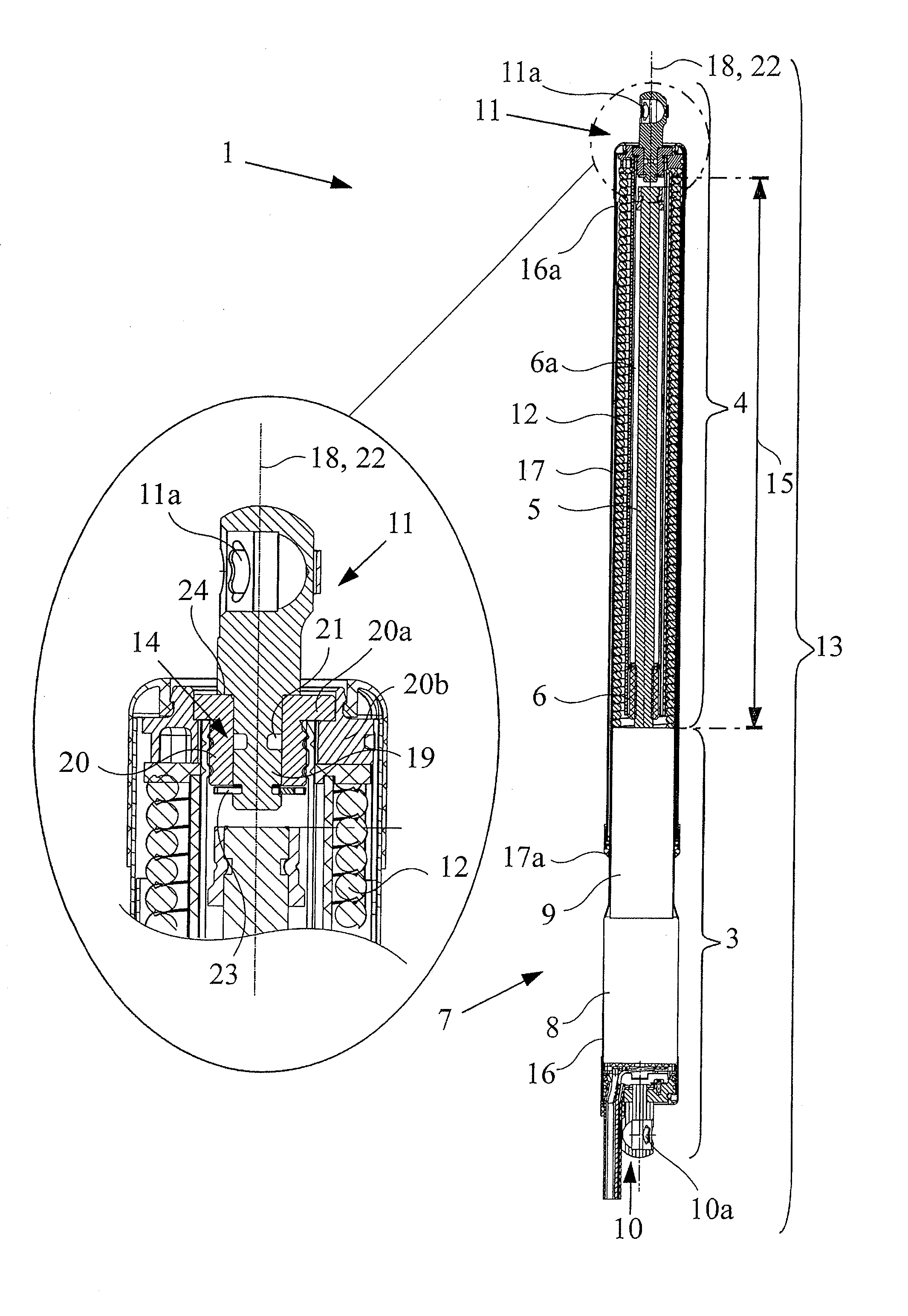
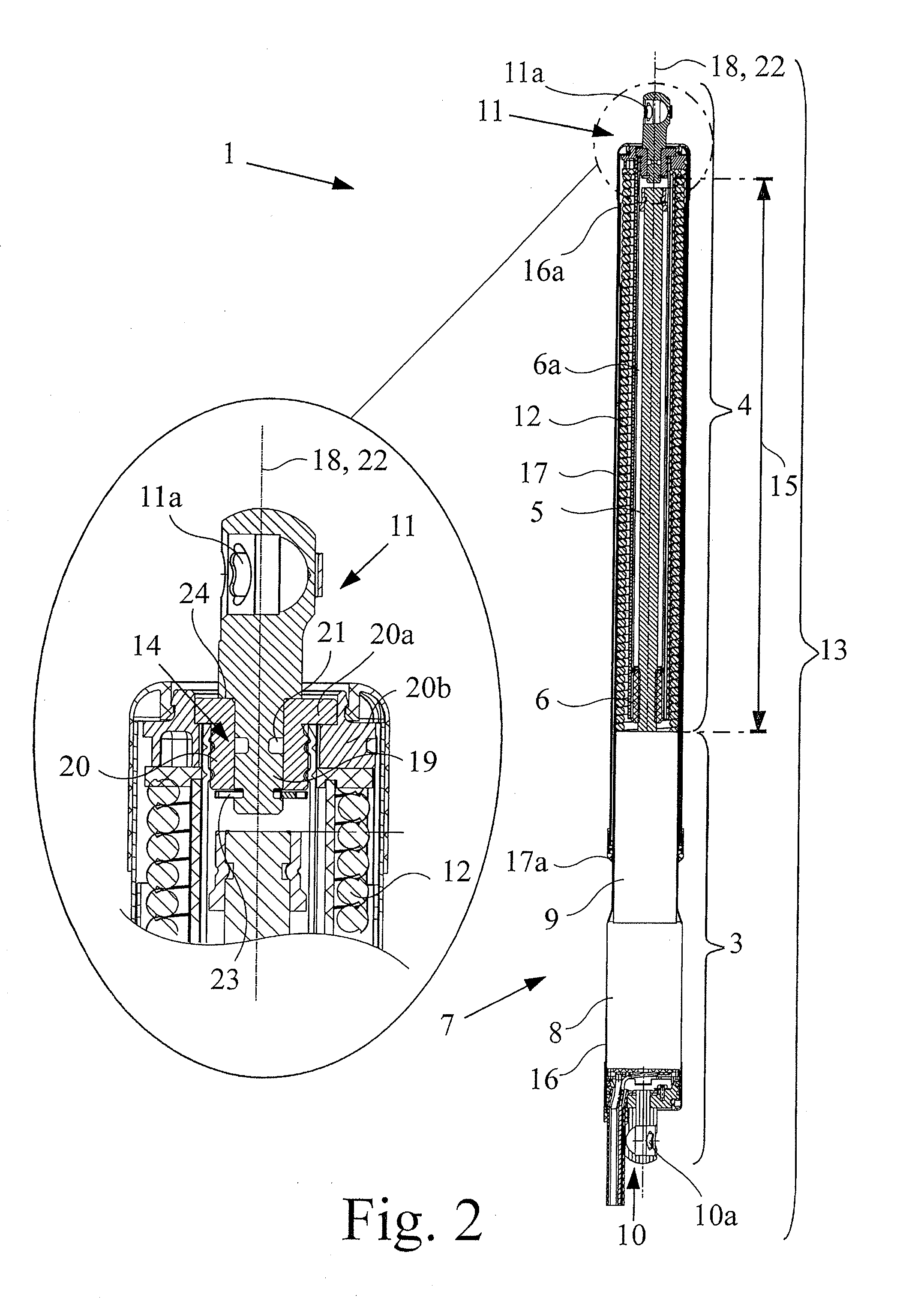
[0033]It may be derived from the view according to FIG. 2 that the spindle drive 1 has a drive portion 3 on the spindle side and a drive portion 4 on the spindle nut side, which are coupled together in terms of ...


PUM


Abstract

Described herein is a spindle drive for the motorized adjustment of an adjustment element of a motor vehicle comprising a drive portion on the spindle side and a drive portion on the spindle nut side, in which the drive portions are able to be adjusted relative to one another in a linear manner for producing drive movements between a refracted position and an extended position and in each case comprising a coupling means for transferring the drive movements and a spring arrangement provided which pretensions the two drive portions in the extended position, wherein a predetermined rupture point is provided in the drive train of the spindle drive which fractures at a predetermined critical load acting via the coupling means on the spindle drive, and which is located outside the flux of force of the spring arrangement.

Description

CROSS-REFERENCE TO RELATED APPLICATIONS[0001]This application claims priority under 35 U.S.C. 119 to German Utility Model Application No. 20 2010 009 334.1, filed Jun. 21, 2010 in the name of Brose Schlieβsysteme GmbH & Co. KG, the disclosure of which is incorporated by reference herein in its entirety.FIELD OF THE INVENTION[0002]The present invention relates to a spindle drive for the motorized adjustment of a motor vehicle. The spindle drive in question may be used for all possible adjustment elements of a motor vehicle. Examples of this are a tailgate, a boot lid, an engine bonnet, a side door, a luggage compartment flap, a raisable roof or the like of a motor vehicle.BACKGROUND[0003]A known spindle drive (DE 20 2008 016 615 U1) on which the invention is based is generally provided with a feed gear mechanism consisting of a spindle and spindle nut, a drive motor being associated with the spindle nut.[0004]Overall, the spindle drive is divided into a drive portion on the spindle s...

Claims


Application Information

Patent Timeline
IPC IPC(8): F16H25/12
CPCE05Y2900/546Y10T74/18576E05F15/622E05Y2600/00E05Y2800/406E05Y2800/424E05Y2800/684
Inventor SCHONHERR, MARCUSDORNEN, JORGSCHNEIDER, ARNE
Owner BROSE SCHLIESSSYSTEME GMBH & CO KG
Why Eureka
Try Eureka