Seat structure and seat contraction method
a seat and seat technology, applied in the direction of movable seats, chairs, dismountable/non-movable seats, etc., can solve the problem of slack at the seat cover end surface of the seat cushion
- Summary
- Abstract
- Description
- Claims
- Application Information
AI Technical Summary
Benefits of technology
Problems solved by technology
Method used
Image
Examples
first embodiment
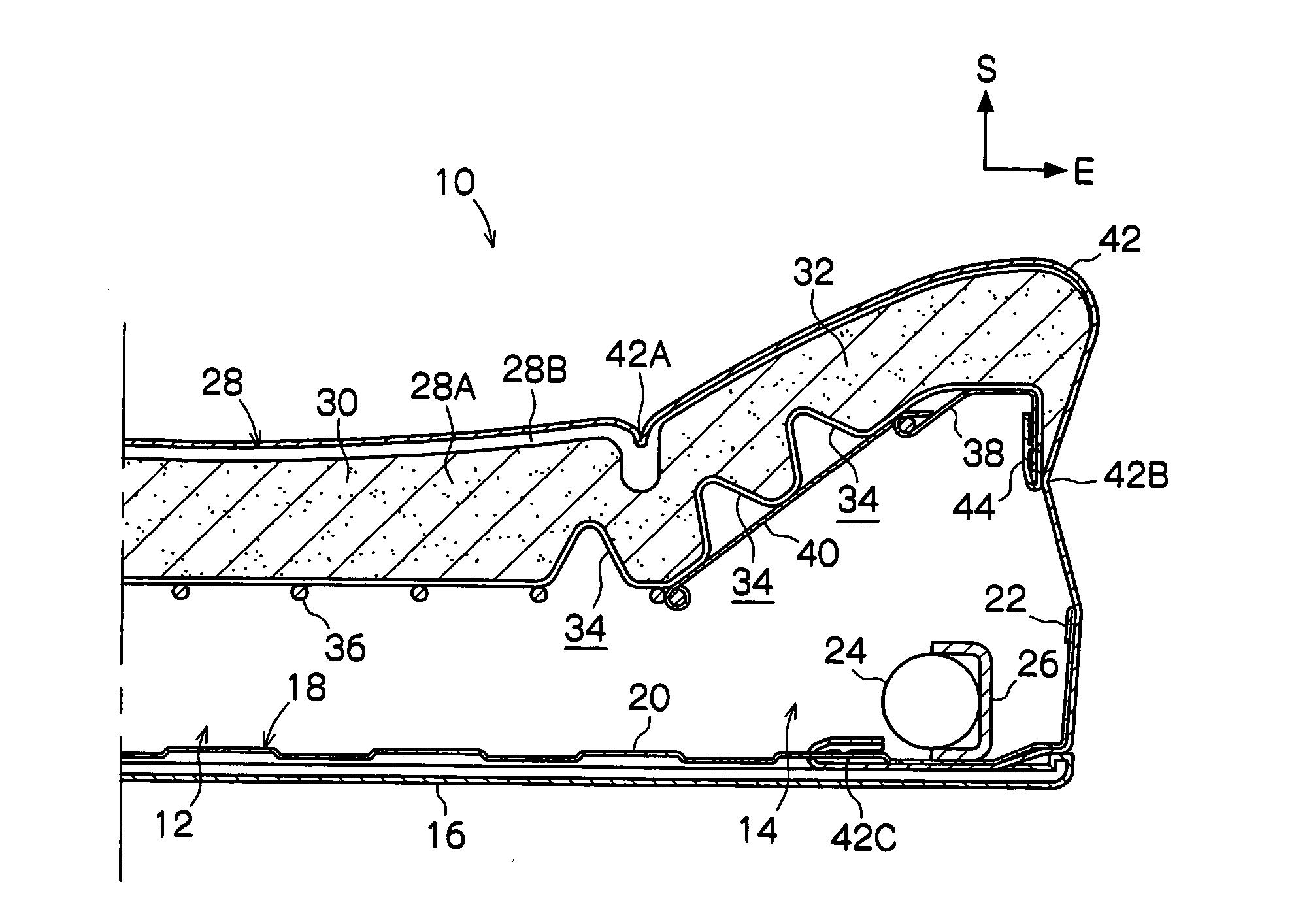
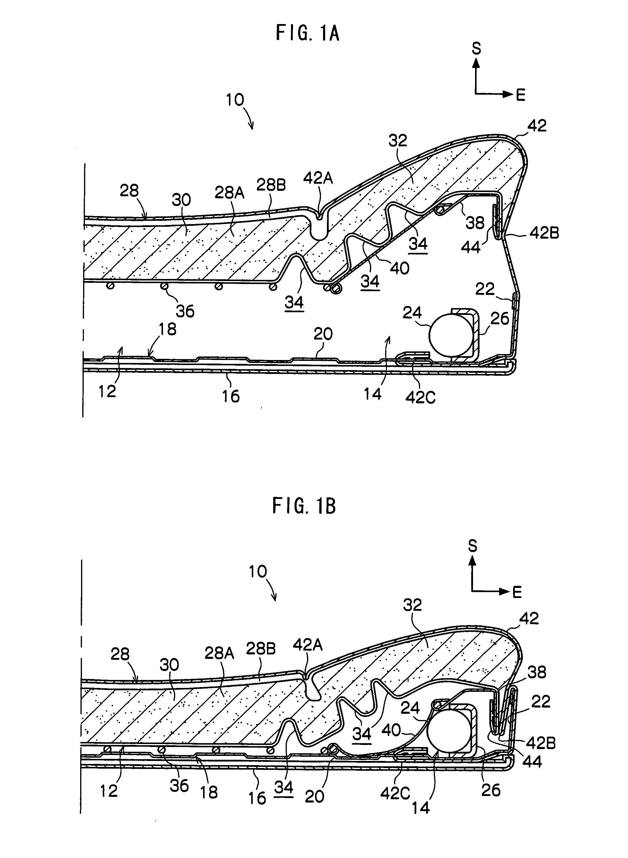
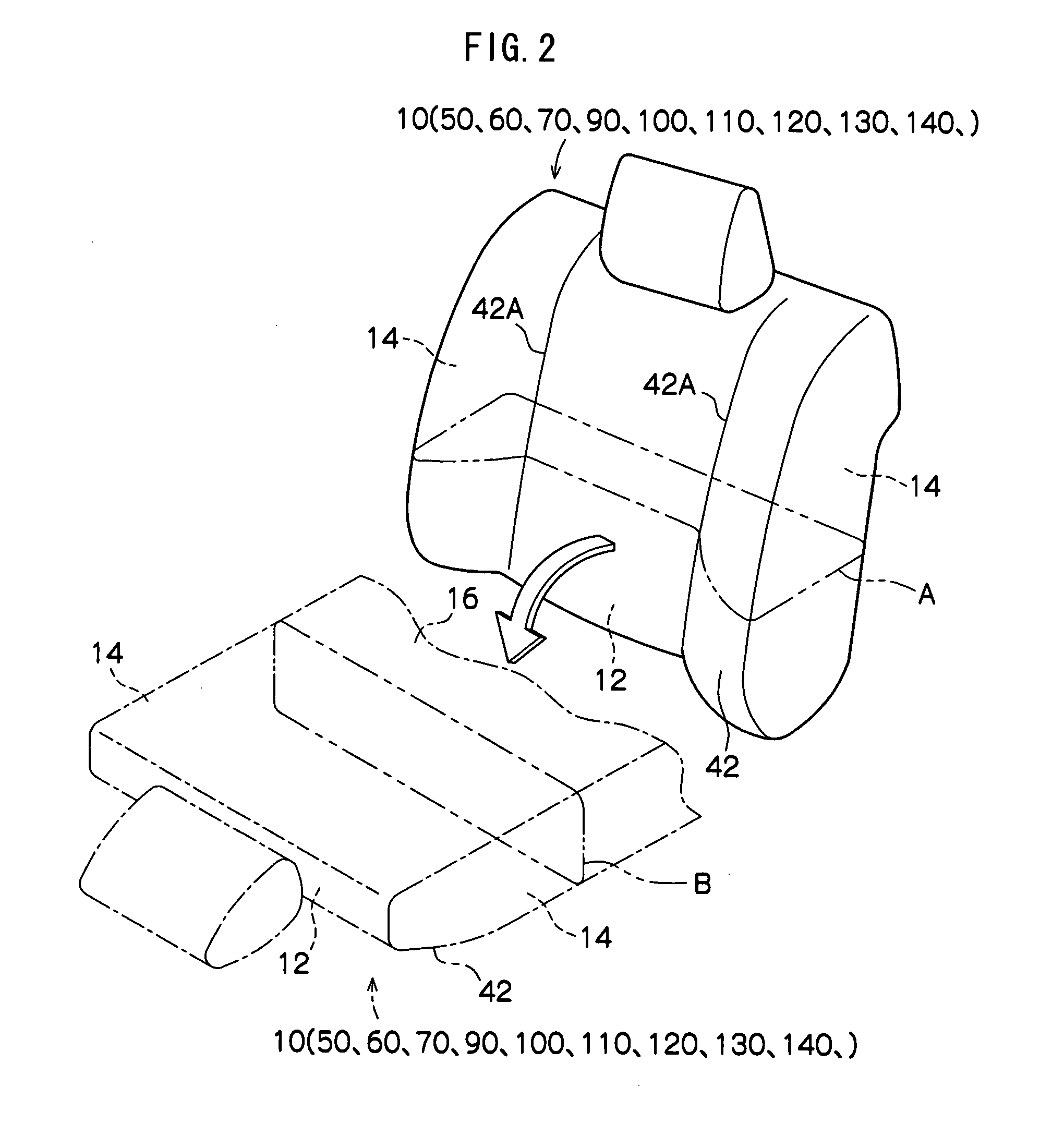
[0065]Main portions of a seat 10, which relates to a first embodiment and which is structured by applying a seat structure and a seat contraction method of the present invention, are shown in a cross-sectional view in FIG. 1A. The seat 10 is shown in FIG. 2 by solid lines in a perspective view seen from an obverse side. Further, in the drawings, the obverse side of the seat 10 is indicated by arrow S, and a lateral direction (transverse direction) outer side of the seat 10 is indicated by arrow E.
[0066]The seat 10 relating to the present embodiment is a seat back of a vehicle. The seat 10 stands substantially vertically from a rear end of a seat cushion of the vehicle (not shown) which is disposed substantially horizontally. As shown by the one-dot chain lines in FIG. 2, the seat 10 is made able to be stowed by being rotated (collapsed forward) around its lower end toward the seat cushion and being superposed on the seat cushion.
[0067]The interior of the lateral direction intermedia...
second embodiment
[0085]Main portions of a seat 50, which relates to a second embodiment and which is structured by applying the seat structure and the seat contraction method of the present invention, are shown in a cross-sectional view in FIG. 3A.
[0086]The seat 50 relating to the present embodiment is substantially the same structure as the above-described first embodiment, but differs with regard to the following points.
[0087]In the seat 50 relating to the present embodiment, the pair of vertical walls 22 are not provided at the wall panel 18.
[0088]The skin 42 covers the seat 50 obverse side surface of the pad center portion 30, the seat 50 obverse side surfaces and lateral direction end surfaces of the pad side portions 32, and the lateral wall 20 of the wall panel 18. The skin 42 is not fixed to the movable plates 38. The final ends 42C of the skin 42 are connected to one ends (the seat 50 lateral direction outer side ends) of tension coil springs 52 (rubber or the like will do) which serve as e...
third embodiment
[0093]Main portions of a seat 60, which relates to a third embodiment and which is structured by applying the seat structure and the seat contraction method of the present invention, are shown in a cross-sectional view in FIG. 4A.
[0094]The seat 60 relating to the present embodiment is substantially the same structure as the above-described first embodiment, but differs with regard to the following points.
[0095]In the seat 60 relating to the present embodiment, the pair of vertical walls 22 are not provided at the wall panel 18.
[0096]The movable plate 38 is extended to the spring 36, and the cotton cloth 40 is not provided. The movable plate 38 functions as the supporting member and supports the concave portion 34 formation portion of the pad side portion 32 from the seat 60 reverse side.
[0097]The skin 42 covers the seat 60 obverse side surface of the pad center portion 30, the seat 60 obverse side surfaces and lateral direction end surfaces of the pad side portions 32, and the later...
PUM
 Abstract
Description
Claims
Application Information
 - R&D
- Intellectual Property
- Life Sciences
- Materials
- Tech Scout
- Unparalleled Data Quality
- Higher Quality Content
- 60% Fewer Hallucinations
Browse by: Latest US Patents, China's latest patents, Technical Efficacy Thesaurus, Application Domain, Technology Topic, Popular Technical Reports.
© 2025 PatSnap. All rights reserved.Legal|Privacy policy|Modern Slavery Act Transparency Statement|Sitemap|About US| Contact US: help@patsnap.com


