Drive braking system of rack-and-pinion vehicle

A technology of braking system and rack car, which is applied in the direction of railway braking system, brake with brake parts, transmission device driven by electric motor, etc., and can solve the problem that the brake drum cannot brake around the rack wheel and there are many parts , The structure of the drum brake device is complicated, etc.

Active Publication Date: 2019-11-15
ZHUZHOU ELECTRIC LOCOMOTIVE CO
View PDF4 Cites 11 Cited by
  • Summary
  • Abstract
  • Description
  • Claims
  • Application Information

AI Technical Summary

Problems solved by technology

Due to the large diameter of the rack wheel and the arrangement of teeth on the outer circumference, the brake drum cannot be braked around the rack wheel
Due to the complex structure and many parts of the drum brake device, how to integrate the drum brake system into the rack wheel drive structure is a technical problem to be solved in this field

Method used


Image

  • Drive braking system of rack-and-pinion vehicle
  • Drive braking system of rack-and-pinion vehicle
  • Drive braking system of rack-and-pinion vehicle

Examples


Embodiment 1

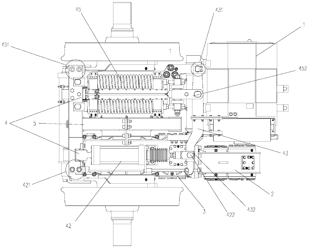
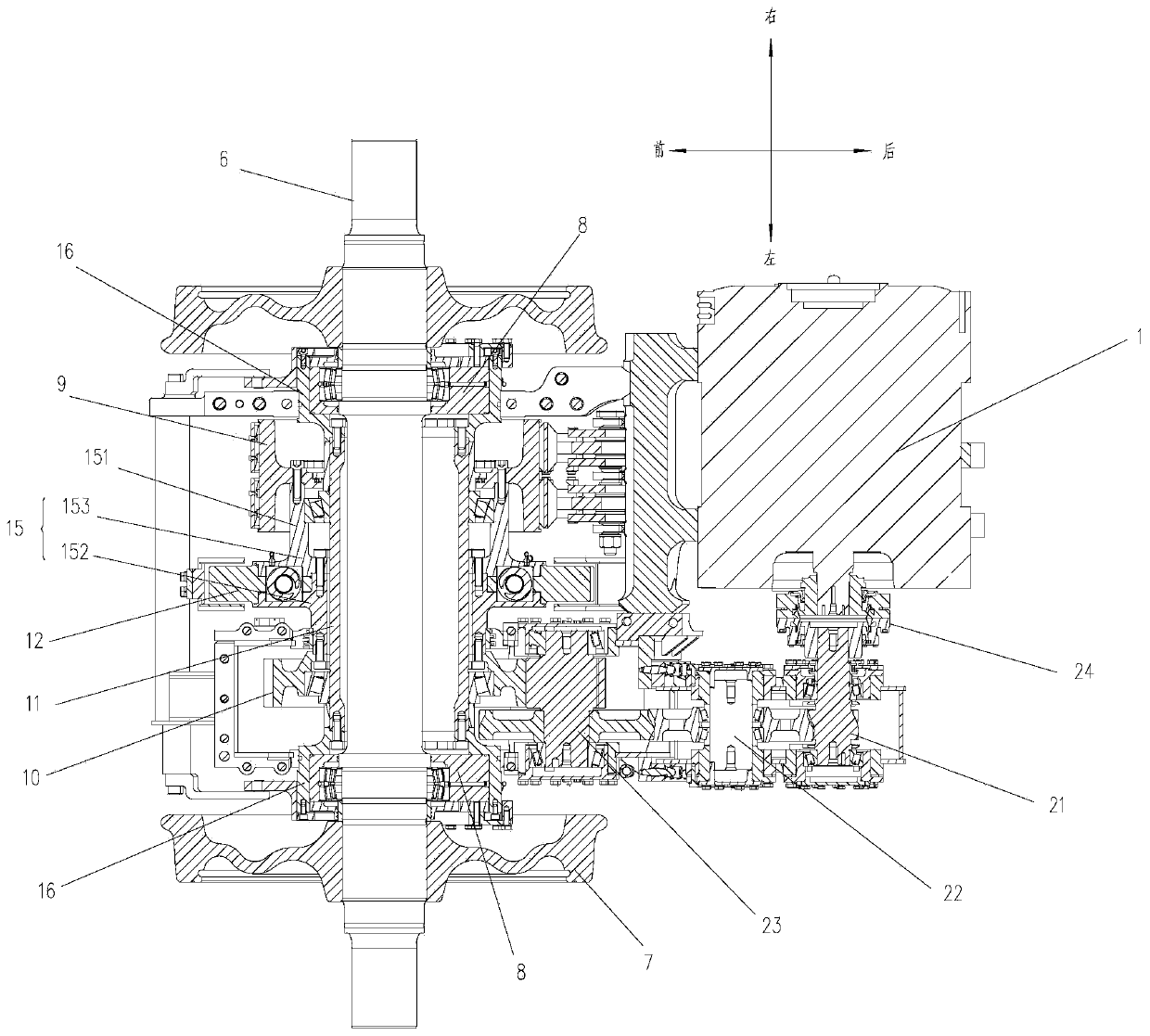
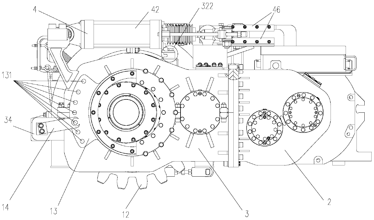
[0039] Such as Figure 1-5 As shown, the rack car driving and braking device in this embodiment includes a gear box 3 , and an axle bridge integrated on the gear box 3 , a rack wheel 12 , a rack wheel base 15 , a driving device and a braking device 4 .

[0040] For convenience, refer to figure 2 and Figure 6 , in this embodiment, the axial direction of the axle is taken as the left-right direction, and the direction perpendicular to the axial direction of the axle is taken as the front-rear direction for illustration.

[0041] Such as Figure 6 and Figure 7 As shown, the gear box for rack vehicles in this embodiment includes a gear box body 32 for installation with the axle bridge of the rack vehicle, and a fixing seat on the right side of the gear box body 32 that is arranged in parallel with the gear box body 32 33. The active gearbox mounting seat 35 located at the rear end of the gearbox body 32, the motor mounting seat 31 connected to the right end of the active ge...


PUM


Abstract

The invention discloses a drive braking system of a rack-and-pinion vehicle. The system comprises a shaft axle, a gear box, a rack-and-pinion wheel, a driving device and a braking device, wherein thegear box is arranged around the shaft axle, the rack-and-pinion wheel is arranged on the shaft axle through a rack-and-pinion wheel seat, the driving device drives the rack-and-pinion wheel to rotate,and the braking device limits rotation of the rack-and-pinion wheel; the driving device comprises a driven gear arranged on the shaft axle, the braking device comprises a brake drum arranged on a hollow shaft, the driven gear and the brake drum are arranged on the two sides of the rack-and-pinion wheel seat correspondingly, and the driven gear is fixedly connected with the rack-and-pinion wheel seat; the end, opposite to the brake drum, of the rack-and-pinion wheel seat extends towards the brake drum to form a mounting part, and the mounting part penetrates into the brake drum and is fixedlyconnected with the brake drum; and the driving device and the braking device are both mounted on the gear box. Therefore, the rack-and-pinion wheel, the driven gear and the brake drum can be connectedinto a whole, the driven gear can be driven by the driving mechanism to drive the rack-and-pinion wheel to rotate, and reliable braking of a device provided with a rack-and-pinion wheel driver can berealized.

Description

technical field [0001] The invention belongs to the technical field of rack car driving, and in particular relates to a rack car driving and braking system. Background technique [0002] The rack car is a mining locomotive that increases the climbing ability by means of the rack on the track bed and the gear on the locomotive. There are a large number of physical locomotives running on different mountain routes abroad. Although there is no rack vehicle running on mountain routes in China, its similar technology has certain applications in the field of amusement facilities and coal mining. [0003] The rack car is suitable for rack lines above 60‰, and has extremely high requirements on the braking system of the vehicle. The drum brake device has the characteristics of large braking torque and is more suitable for braking rack cars. Due to the large diameter of the rack wheel and the arrangement of teeth on the outer periphery, the brake drum cannot be braked around the ra...

Claims


Application Information

Patent Timeline
Patent Type & Authority Applications(China)
IPC IPC(8): B61H1/00B61C9/38B61B13/02
CPCB61B13/02B61C9/38B61H1/006
Inventor 陈喜红陶功安张又孔廖志伟李冠军沈龙江陈国胜易兴利李振华郭庆升谢加辉祝贺党春梅
Owner ZHUZHOU ELECTRIC LOCOMOTIVE CO
Why Eureka
Try Eureka