Vortex generator for reducing resistance of fuselage and delaying airflow separation

A vortex generator and airflow separation technology, which is applied in drag reduction, aircraft parts, aircraft control, etc., can solve the problems of increasing fuselage resistance, rotor power consumption, crashing, etc.

Pending Publication Date: 2019-11-15
NANJING UNIV OF AERONAUTICS & ASTRONAUTICS
View PDF0 Cites 8 Cited by
  • Summary
  • Abstract
  • Description
  • Claims
  • Application Information

AI Technical Summary

Problems solved by technology

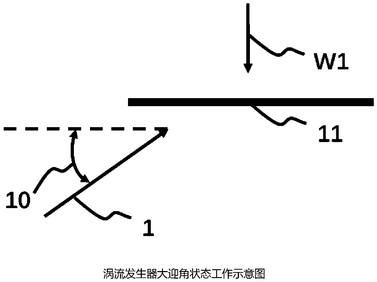
[0003] Among them, the crosswind flow is a more difficult problem in the drag reduction design of the rotorcraft. When the rotorcraft is in the crosswind flow situation, the fuselage in this state is not streamlined relative to the incoming flow. At this time, the flow field of the fusela...

Method used


Image

  • Vortex generator for reducing resistance of fuselage and delaying airflow separation
  • Vortex generator for reducing resistance of fuselage and delaying airflow separation
  • Vortex generator for reducing resistance of fuselage and delaying airflow separation

Examples


Embodiment Construction

[0029] In order to enable those skilled in the art to better understand the technical solutions of the present invention, the present invention will be further described in detail below in conjunction with the accompanying drawings and specific embodiments. Hereinafter, embodiments of the present invention will be described in detail, examples of which are shown in the accompanying drawings, wherein the same or similar reference numerals denote the same or similar elements or elements having the same or similar functions throughout. The embodiments described below by referring to the figures are exemplary only for explaining the present invention and should not be construed as limiting the present invention. Those skilled in the art will understand that unless otherwise stated, the singular forms "a", "an", "said" and "the" used herein may also include plural forms. It should be further understood that the word "comprising" used in the description of the present invention refe...


PUM


Abstract

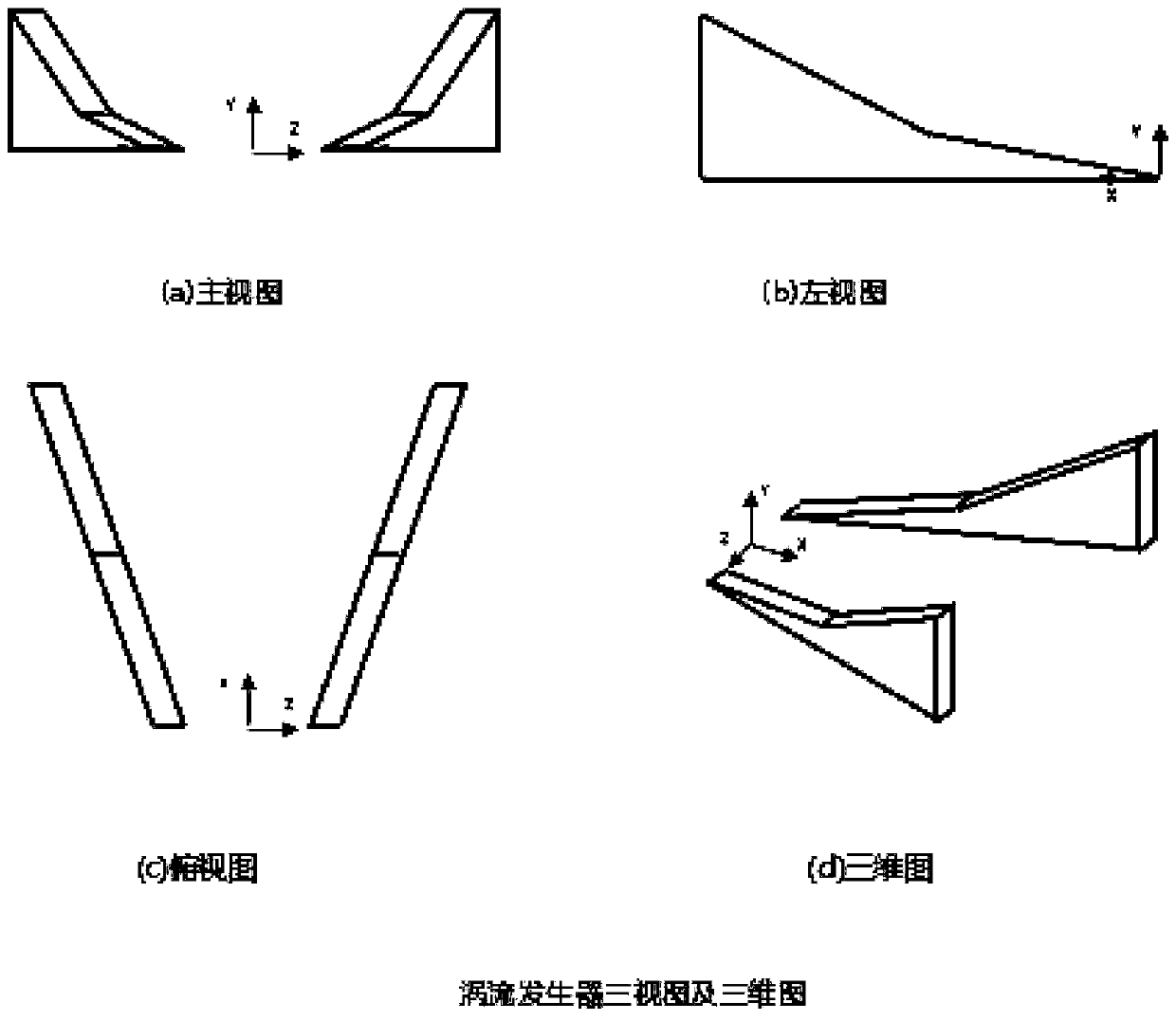
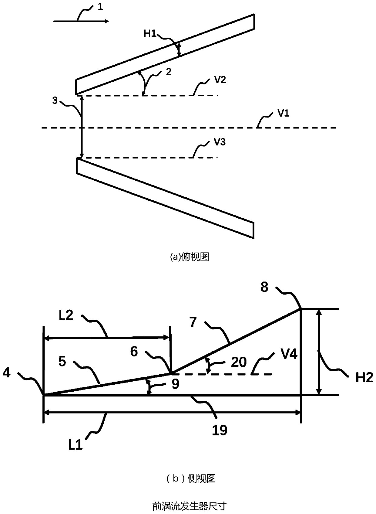
The embodiment of the invention discloses a vortex generator for reducing resistance of a fuselage and delaying airflow separation, and relate to the technical field of rotor aircraft manufacturing. According to the vortex generator, the passive control for the flowing of a flow field near the fuselage can be realized when a rotor aircraft encounters strong cross-wind or carries out side flight, so that the resistance of the rotor aircraft is reduced, and meanwhile, the implementation cost and the failure rate are reduced. The vortex generator provided by the invention comprises an installation angle (2) of the vortex generator, a first corner (9) of a single-chip vortex generator and a second corner (20) of the single-chip vortex generator, wherein a value of the installation angle (2) ofthe vortex generator is larger than or equal to 10 degrees and less than or equal to 45 degrees; the second corner (20) of the single-chip vortex generator is an included angle between an upper surface (7) of the second section and a connecting section (19) of the vortex generator and the object surface; a value of the first corner (9) of the single-chip vortex generator is less than 30 degrees;and a value of the second corner (20) is larger than or equal to 40 degrees and less than or equal to 60 degrees. The vortex generator is suitable for the passive control for the flow of the flow field near the fuselage when the rotor aircraft encounters the strong cross-wind or carries out side flight.

Description

technical field [0001] The invention relates to the technical field of rotorcraft manufacturing, in particular to a vortex generator used for reducing drag on a fuselage and delaying airflow separation. Background technique [0002] In many application fields, rotorcraft is irreplaceable. With the continuous improvement of the speed of the rotorcraft, it is more and more important to reduce the drag of the rotorcraft. Generally speaking, the waste drag of the rotorcraft fuselage can account for 25% to 30% of the total aircraft waste drag, so it is very necessary to carry out drag reduction work on the rotorcraft fuselage. [0003] Among them, the crosswind flow is a more difficult problem in the drag reduction design of the rotorcraft. When the rotorcraft is in the crosswind flow situation, the fuselage in this state is not streamlined relative to the incoming flow. At this time, the flow field of the fuselage is easy. A large airflow separation area occurs, which greatly ...

Claims


Application Information

Patent Timeline
IPC IPC(8): B64C23/06
CPCB64C23/06B64C2230/04Y02T50/10
Inventor 招启军林沐阳王博周旭陈希
Owner NANJING UNIV OF AERONAUTICS & ASTRONAUTICS
Why Eureka
Try Eureka