A drag reduction device and drag reduction method based on periodic stepped cylinder

A drag reduction device and periodic technology, applied in the direction of shafts and bearings, bearing components, mechanical equipment, etc., can solve the problems of high cost, reduce the resistance of the rotating shaft, can not be obtained, etc., achieve significant drag reduction effect, reduce resistance, and facilitate processing Effect

Active Publication Date: 2020-05-01
NORTHWESTERN POLYTECHNICAL UNIV
View PDF6 Cites 0 Cited by
  • Summary
  • Abstract
  • Description
  • Claims
  • Application Information

AI Technical Summary

Problems solved by technology

Although this method can obtain a stable drag reduction, it is difficult to process the grooves on the rotor surface, the cost is relatively high, and a significant drag reduction cannot be obtained.
At present, there is no better method in the field of industrial applications that can effectively and continuously reduce the resistance between the shaft and the shaft sleeve
And can not obtain more significant effect of effectively and continuously reducing the resistance between the rotating shaft and the shaft sleeve

Method used


Image

  • A drag reduction device and drag reduction method based on periodic stepped cylinder
  • A drag reduction device and drag reduction method based on periodic stepped cylinder

Examples


Embodiment Construction

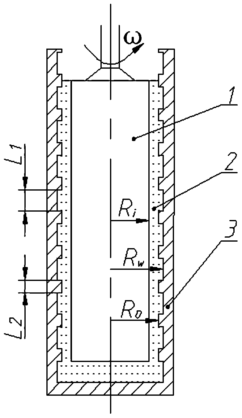
[0026] This embodiment is a drag reducing device and a drag reducing method based on a periodic stepped cylinder; the drag reducing device and the drag reducing method are based on the periodicity of the Taylor vortex rotating in reverse under the Taylor-Couette flow condition, changing the size of the Taylor vortex , to reduce the number of large-sized Taylor vortices, by arranging periodic cylindrical surfaces with different radii in the axial direction on the inner surface of the sleeve, the size and number of Taylor vortices are modulated, so that the size of Taylor vortices changes, and the number of large-sized Taylor vortices decreases, so that Reduce the resistance of the shaft. When the shaft is rotating, the circumferential flow of lubricating liquid between the shaft and the bushing belongs to Taylor-Couette flow, because the size of a pair of counter-rotating Taylor vortices is equal to twice the gap between the shaft and the bushing. When the size of a pair of cou...


PUM


Abstract

The invention discloses a damping device and a damping method based on the periodical step cylindrical surface. According to the damping device and the damping method, through the periodicity of reverse rotating Taylor vortices under the Taylor-Couette flow conditions, the size of the Taylor vortices is changed, and the number of the big-size Taylor vortices is reduced. By arranging periodical cylindrical surfaces with different radii on the inner wall of a shaft sleeve in the axial direction and controlling the height of the liquid level in the gap between a rotary shaft and the shaft sleeveduring Taylor-Couette flow, the rotating speed of the rotary shaft and the injection speed of working fluid are controlled to achieve the hysteresis effect of the Taylor vortices under different injection speeds. By slowly increasing the liquid level height of the working fluid between the rotary shaft and the shaft sleeve, the size and number of the Taylor vortices are changed, so that the size of the Taylor vortices is changed, and the number of the big-size Taylor vortices is reduced. Accordingly, resistance of the rotary shaft is reduced. The damping device has the characteristics that thedamping device is fast and convenient to manufacture and low in cost, and the damping method is remarkable in damping effect.

Description

technical field [0001] The invention relates to a liquid lubricated rotating shaft drag reduction technology, in particular to a drag reduction device and a drag reduction method based on a periodically stepped cylindrical surface. Background technique [0002] Liquid-lubricated rotating shafts and bushings are widely used in basic research and engineering fields as a classic lubricated drag-reducing rotation. How to reduce the frictional resistance caused by the rotation of the rotating shaft is particularly important in the field of engineering applications. In 2015, A.J.Greidanus1 et al. (Turbulent Taylor–Couette flow over riblets: drag reduction and the effect of bulk fluid rotation [J]. Experiments in Fluids, 2015, 56(5): 107.) constructed a micron-scale rotor surface in a cylinder The maximum drag reduction rate of the trench is 5.3%. Although this method can obtain a stable drag reduction, it is difficult to process grooves on the rotor surface, the cost is relative...

Claims


Application Information

Patent Timeline
Patent Type & Authority Patents(China)
IPC IPC(8): F16C33/04
CPCF16C33/04
Inventor 胡海豹张文云文俊鲍路瑶杜鹏任刘珍黄潇
Owner NORTHWESTERN POLYTECHNICAL UNIV
Why Eureka
Try Eureka