
Positioning plate for butt joint of steel columns and steel column welding and installation method

An installation method and positioning board technology, which is applied in the field of positioning boards, can solve the problems of steel columns that cannot be accurately positioned, poor working environment, and slow installation process, and achieve the effects of improving installation speed and construction quality, reducing construction costs, and simple structure

Inactive Publication Date: 2019-11-15
CHINA HUAYE GROUP +1
View PDF6 Cites 7 Cited by
  • Summary
  • Abstract
  • Description
  • Claims
  • Application Information

AI Technical Summary

Problems solved by technology

However, when the steel column is hoisted mechanically, the steel column often swings back and forth so that it cannot be positioned accurately, resulting in a slow installation process
Moreover, due to the high installation position and the harsh working environment, if the command personnel and the installation personnel do not cooperate properly, safety accidents such as collisions and falls are prone to occur, resulting in casualties

Method used


Image

  • Positioning plate for butt joint of steel columns and steel column welding and installation method
  • Positioning plate for butt joint of steel columns and steel column welding and installation method
  • Positioning plate for butt joint of steel columns and steel column welding and installation method

Examples


Embodiment 1

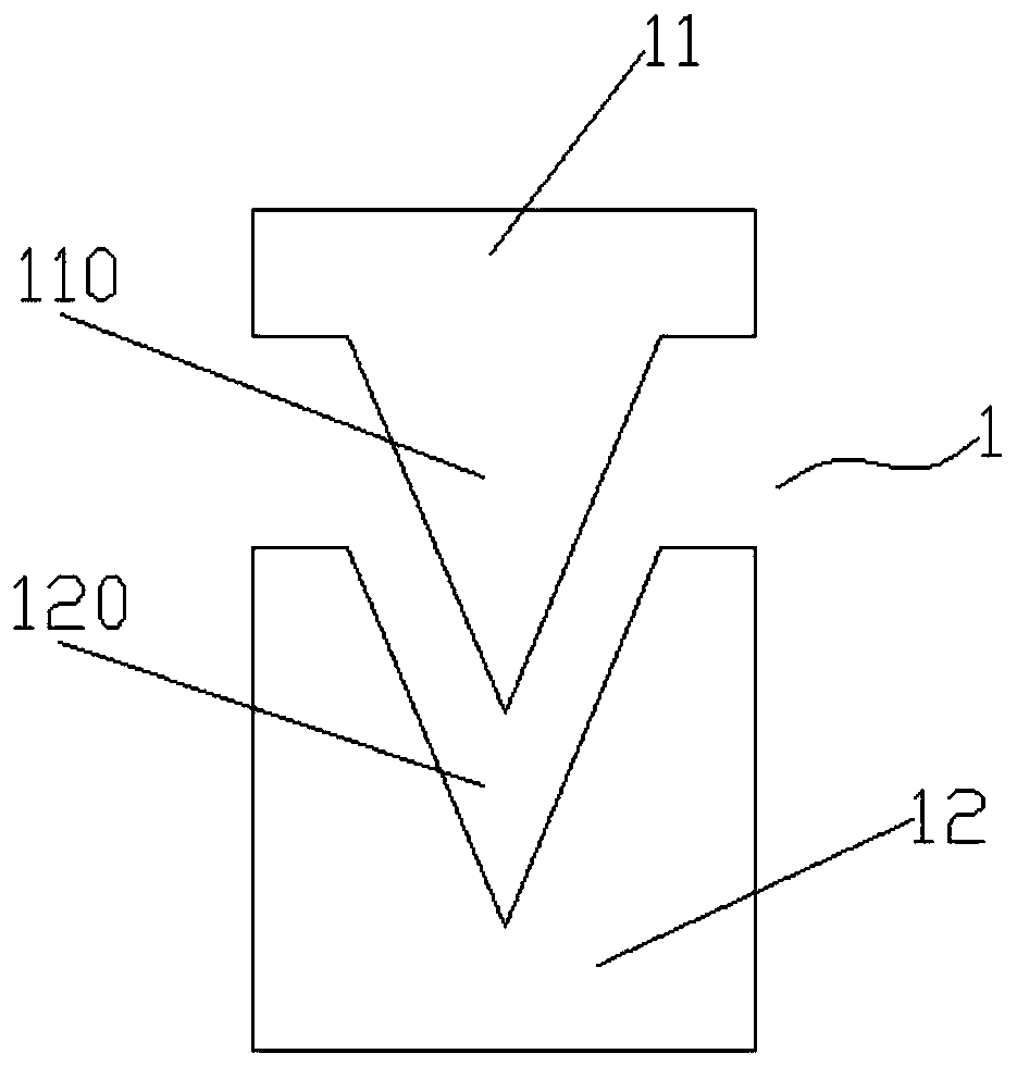
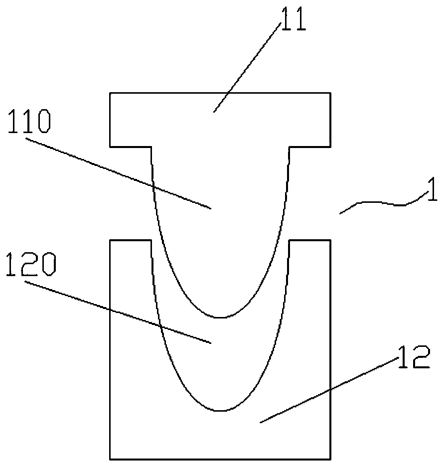
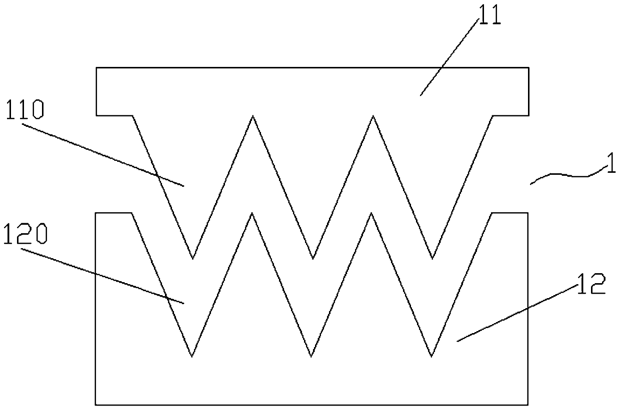
[0028] figure 1 It is a schematic diagram showing the first structure of the positioning plate for steel column butting involved in an embodiment of the present invention. figure 2 It is a schematic diagram showing the second structure of the positioning plate for steel column butting involved in an embodiment of the present invention. image 3 It is a schematic diagram showing the third structure of the positioning plate for steel column butting involved in an embodiment of the present invention. Figure 4 It is a schematic diagram showing the fourth structure of the positioning plate for steel column butting involved in an embodiment of the present invention.

[0029] Such as figure 1 As shown, in this embodiment of the present invention, the positioning plate 1 for steel column butting includes a first connecting plate 11 and a second connecting plate 12. A raised portion 110 is provided on one side of the first connecting plate 11, and a concave portion 120 that matches the ab...

Embodiment 2

[0035] Figure 5 It is a schematic diagram showing the structure of the steel column involved in an embodiment of the present invention during installation.

[0036] reference Figure 5 , To introduce the steel column installation method in this embodiment. The installation method is used to install the upper and lower steel columns. The steel columns can be box-shaped columns, cross-shaped columns, or H-shaped columns. This installation method can be applied to at least two sides of the upper and lower steel columns in the same plane. This embodiment describes the installation method by taking a box-shaped column as an example. The specific installation method includes the following steps:

[0037] Step S1: According to the size of the steel column, the positioning plate 1 described in the first embodiment is produced, wherein the width of the positioning plate 1 should be between one quarter and one half of the width of the side of the steel column. In this embodiment, the upp...


PUM


Abstract

The invention discloses a positioning plate for butt joint of steel columns. The positioning plate comprises a first connecting plate and a second connecting plate, wherein a plurality of protrusionsare arranged on one side edge of the first connecting plate, a plurality of concave parts matched with the protrusions are arranged on one side edge of the second connecting plate, and the first connecting plate and the second connecting plate can be attached through the protrusions and the concave parts. The invention further discloses a welding and installation method for upper and lower steel columns by using the positioning plate. The first connecting plate and the second connecting plate of the positioning plate are mounted on the side faces of butt-joint parts of the two steel columns respectively, and the steel columns can be quickly positioned through insertion fit of the first connecting plate and the second connecting plate.

Description

Technical field [0001] The invention relates to the technical field of steel structure construction, and in particular to a positioning plate used when two steel columns are butted and an installation method when two steel columns are butted. Background technique [0002] In the current high-rise frame steel structure construction, steel columns (such as box columns, cross columns, and H-shaped steel columns) are usually made in sections and spliced ​​on site. When the upper and lower steel columns are connected and installed, first draw a positioning line on the side of the steel column, hoist the steel column to be installed above the installed steel column, and then lift the upper steel column by measuring tools and mechanical lifting methods. Installed on the lower steel column, this process requires the operator to adjust the position of the steel column back and forth in the high altitude according to the requirements of the surveying personnel to ensure the verticality of ...

Claims


Application Information

Patent Timeline
Patent Type & Authority Applications(China)
IPC IPC(8): E04B1/24E04B1/58
CPCE04B1/2403E04B2001/2406E04B2001/246
Inventor 王海薛志彬
Owner CHINA HUAYE GROUP
Learn More