Door closing device for aluminum-coated wooden door
A technology for door closers and wooden doors, which can be used in wing closers, door/window accessories, wing openers, etc., and can solve the problems of low structural strength of moving parts, complex structure of door closers, and short service life. , to achieve the effect of small footprint, high tensile strength and yield strength, and extended service life
- Summary
- Abstract
- Description
- Claims
- Application Information
AI Technical Summary
Problems solved by technology
Method used
Image
Examples
Embodiment 1
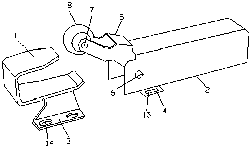
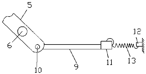
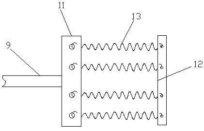
[0026] like Figure 1-3 As shown, a door closer for an aluminum-clad wooden door includes a stopper 1 and a housing 2. The stopper 1 is arranged in a U shape, and a horizontal installation block 3 extends downward from one side of the stopper 1. Both sides of the housing 2 are horizontally provided with mounting plates 4, and the front end of the housing 2 is provided with a movable seat 5 and a first rotating shaft 6, and one side of the movable seat 5 moves with the middle part of the front end of the housing 2 through the first rotating shaft 6. Connected, the middle part of the movable seat 5 is upwardly protruding, and the end of the movable seat 5 away from the housing 2 is equipped with a roller 8 through the second rotating shaft 7, and the roller 8 is correspondingly arranged in the block 1, and the movable One end of the seat 5 close to the housing 2 is provided with a connecting rod 9 and a third rotating shaft 10, the connecting rod 9 is installed in the movable se...
Embodiment 2
[0040] Such as Figure 1-3 As shown, a door closer for an aluminum-clad wooden door includes a stopper 1 and a housing 2. The stopper 1 is arranged in a U shape, and a horizontal installation block 3 extends downward from one side of the stopper 1. Both sides of the housing 2 are horizontally provided with mounting plates 4, and the front end of the housing 2 is provided with a movable seat 5 and a first rotating shaft 6, and one side of the movable seat 5 moves with the middle part of the front end of the housing 2 through the first rotating shaft 6. Connected, the middle part of the movable seat 5 is upwardly protruding, and the end of the movable seat 5 away from the housing 2 is equipped with a roller 8 through the second rotating shaft 7, and the roller 8 is correspondingly arranged in the block 1, and the movable One end of the seat 5 close to the housing 2 is provided with a connecting rod 9 and a third rotating shaft 10, the connecting rod 9 is installed in the movable...
Embodiment 3
[0054] Such as Figure 1-3 As shown, a door closer for an aluminum-clad wooden door includes a stopper 1 and a housing 2. The stopper 1 is arranged in a U shape, and a horizontal installation block 3 extends downward from one side of the stopper 1. Both sides of the housing 2 are horizontally provided with mounting plates 4, and the front end of the housing 2 is provided with a movable seat 5 and a first rotating shaft 6, and one side of the movable seat 5 moves with the middle part of the front end of the housing 2 through the first rotating shaft 6. Connected, the middle part of the movable seat 5 is upwardly protruding, and the end of the movable seat 5 away from the housing 2 is equipped with a roller 8 through the second rotating shaft 7, and the roller 8 is correspondingly arranged in the block 1, and the movable One end of the seat 5 close to the housing 2 is provided with a connecting rod 9 and a third rotating shaft 10, the connecting rod 9 is installed in the movable...
PUM
 Abstract
Description
Claims
Application Information
 - R&D
- Intellectual Property
- Life Sciences
- Materials
- Tech Scout
- Unparalleled Data Quality
- Higher Quality Content
- 60% Fewer Hallucinations
Browse by: Latest US Patents, China's latest patents, Technical Efficacy Thesaurus, Application Domain, Technology Topic, Popular Technical Reports.
© 2025 PatSnap. All rights reserved.Legal|Privacy policy|Modern Slavery Act Transparency Statement|Sitemap|About US| Contact US: help@patsnap.com


