
Steel beam fixing structure

A technology for fixing structures and steel beams, applied in shaft equipment, mining equipment, earthwork drilling and mining, etc., can solve the problems of reducing the bearing capacity of supporting plates and steel beams, mismatching steel beam dimensions, and unguaranteed installation quality, etc., to achieve Reduced installation work intensity, low labor work intensity, and improved rigidity

Pending Publication Date: 2019-11-15
CHINA ENFI ENGINEERING CORPORATION
View PDF0 Cites 0 Cited by
  • Summary
  • Abstract
  • Description
  • Claims
  • Application Information

AI Technical Summary

Problems solved by technology

[0003] However, with the improvement of mine capacity, especially in the hoisting shaft, the steel beams bear more and more stress. At this time, the angle steel support plate appears very thin, and it does not match the shape and size of the "tall" steel beams, which affects visual safety.
At the same time, the fixed structure of the upper and lower angle steel pallets is affected by the quality of the on-site construction. It is often necessary to ream the holes on the pallet or steel beams on site. Affected by the size of the angle steel, the size of the reaming holes is limited, difficult to install, and the on-site reaming is also greatly The bearing capacity of the supporting plate and the steel beam is reduced, so that the installation quality cannot be guaranteed
In addition, due to the on-site electric welding and reaming in the underground, the construction progress is seriously affected, and it is not conducive to the safety of the constructors.

Method used


Image

  • Steel beam fixing structure
  • Steel beam fixing structure
  • Steel beam fixing structure

Examples


Embodiment Construction

[0034] Embodiments of the present invention are described in detail below, examples of which are shown in the drawings, wherein the same or similar reference numerals designate the same or similar elements or elements having the same or similar functions throughout. The embodiments described below by referring to the figures are exemplary only for explaining the present invention and should not be construed as limiting the present invention.

[0035] In the description of the present invention, it should be understood that the orientation or positional relationship indicated by the terms "upper", "lower", "length", "vertical", "horizontal" etc. is based on the orientation or position shown in the drawings The relationship is only for the convenience of describing the present invention and simplifying the description, but does not indicate or imply that the referred device or element must have a specific orientation, be constructed and operated in a specific orientation, and thu...


PUM


Abstract

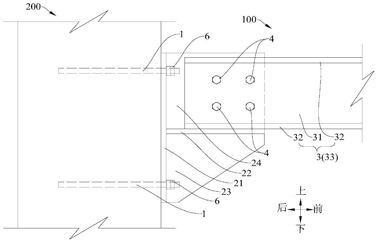
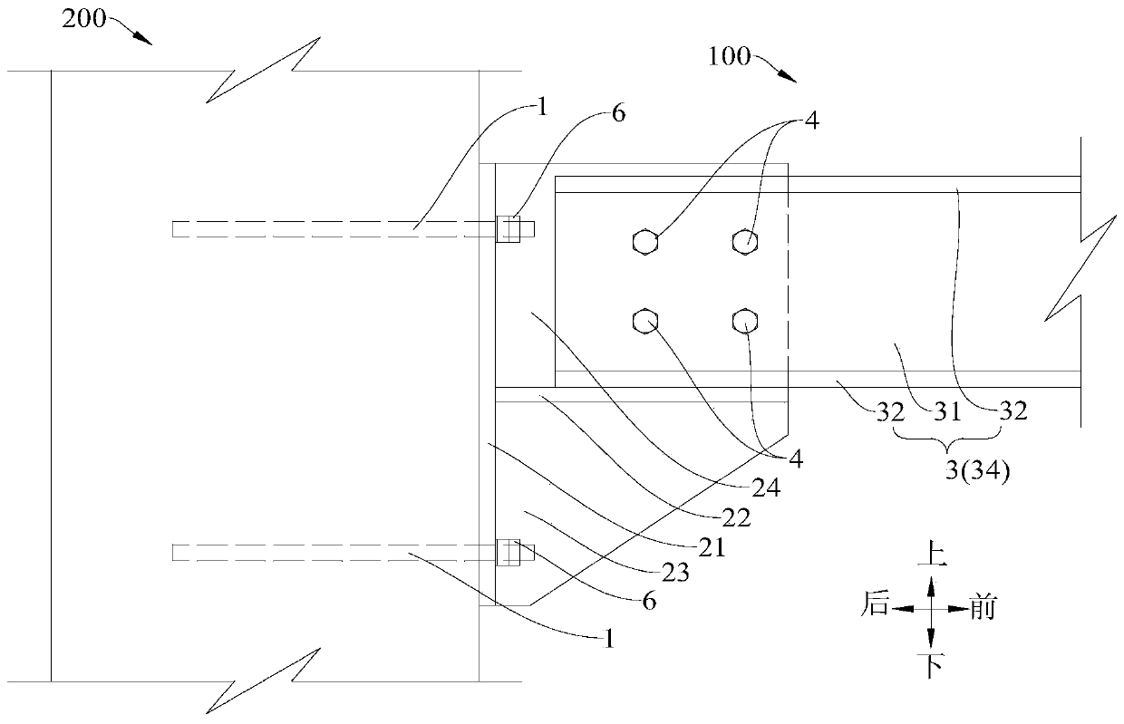
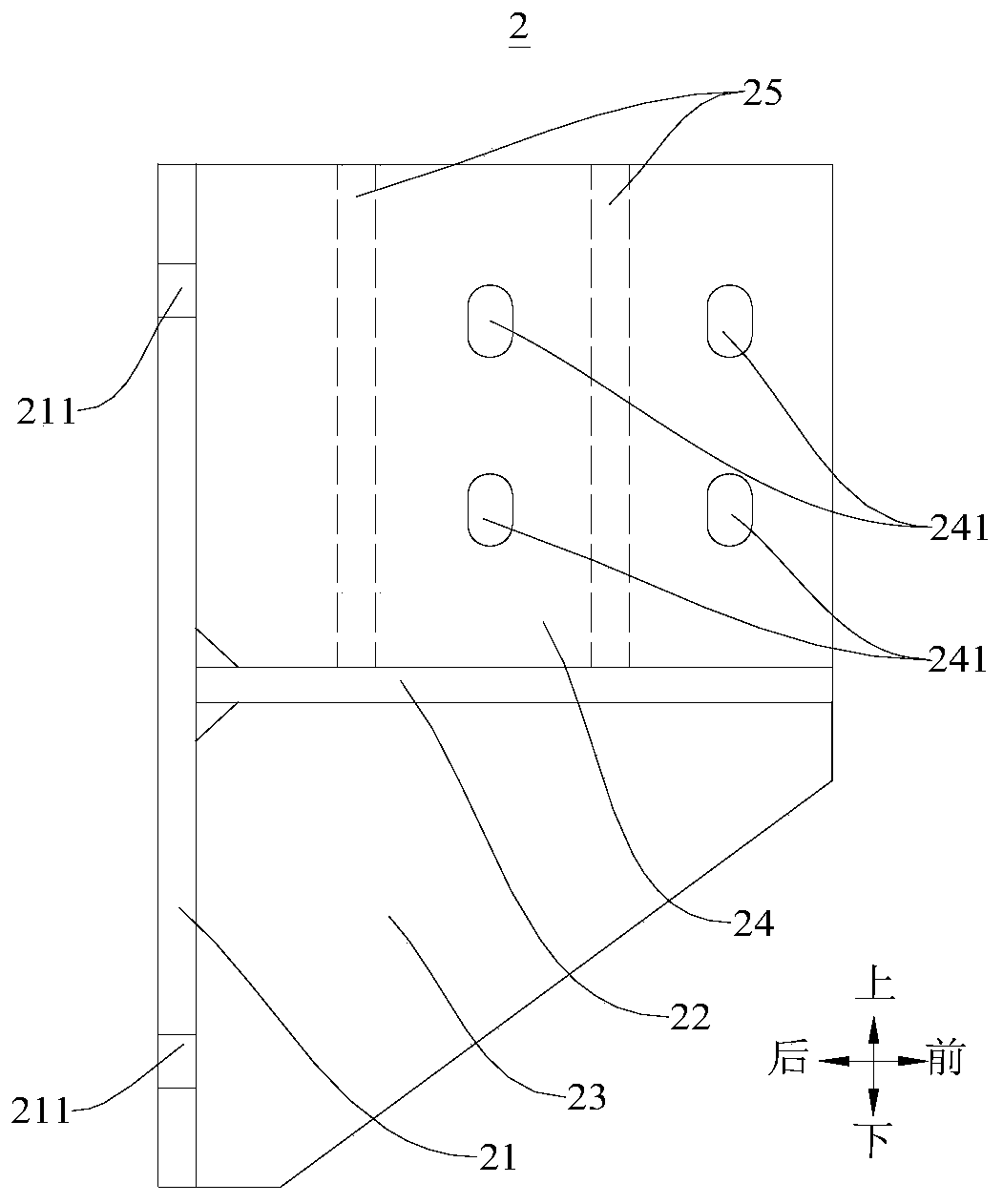
The invention discloses a steel beam fixing structure. The steel beam fixing structure comprises anchor rods, a welding bracket, a steel beam and bolts, wherein the anchor rods are suitable for beinganchored on the well wall; the welding bracket comprises a side plate, a flat plate, a vertical plate and stiffening ribs, the side plate is arranged along the well wall and connected with the anchorrods to be fixed to the well wall, the flat plate is connected to one side of the side plate, the vertical plate is vertically arranged on the flat plate and connected with the side plate, a first connecting hole is formed in the vertical plate, and the stiffening ribs are located on one horizontal side of the vertical plate and connected with the vertical plate and the flat plate correspondingly;the steel beam is arranged on the flat plate and located on the other horizontal side of the vertical plate, and a second connecting hole is formed in the steel beam; and the bolts penetrate throughthe first connecting hole and the second connecting hole correspondingly so as to connect the steel beam with the welding bracket. According to the steel beam fixing structure, the bearing capacity ofthe steel beam can be improved, and the safety of mounting construction is improved.

Description

technical field [0001] The invention relates to the field of mechanical structures for mine shaft equipment, in particular to a steel beam fixing structure. Background technique [0002] In the related art, the fixing structure between the steel beam and the well wall is mainly to open holes on the steel beam flange, and then connect with the angle steel supporting plate, and the angle steel supporting plate is fixed on the well wall through anchor rods. When the force of the channel steel beam increases, it is necessary to weld angle steel on the web of the steel beam, and the angle steel is flush with the wing plate of the steel beam, and then connected with the angle steel bracket by bolts. This fixed structure is often used when the steel beam is under small stress. [0003] However, with the improvement of mine capacity, especially in the hoisting shaft, the steel beams bear more and more stress. At this time, the angle steel support plate appears very thin, and it doe...

Claims


Application Information

Patent Timeline
Patent Type & Authority Applications(China)
IPC IPC(8): E21D7/00
CPCE21D7/00
Inventor 郭相参安建英徐长磊过曾明孙扬
Owner CHINA ENFI ENGINEERING CORPORATION
Learn More