A shield machine cutterhead with variable cutter spacing
A technology of shield machine and cutter head, which is applied in the field of shield machine, can solve the problem of invariable spacing between hobs, and achieve the effects of reducing construction difficulty, prolonging tool life, and reducing construction costs
- Summary
- Abstract
- Description
- Claims
- Application Information
AI Technical Summary
Problems solved by technology
Method used
Image
Examples
Embodiment 1
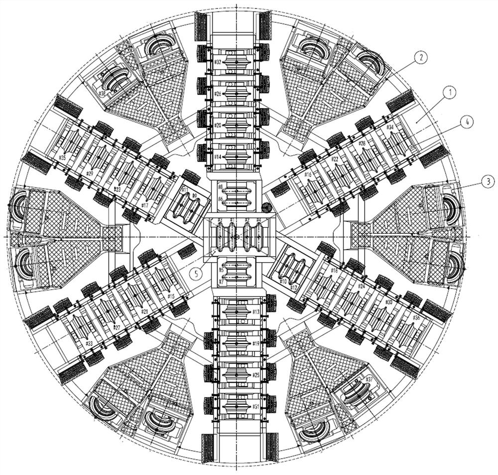
[0022] Embodiment 1, a shield machine cutterhead with variable cutter spacing, such as figure 1 As shown, including the main beam 1 of the cutter head, the hob assembly 4 is adjustable inside the main beam 1 of the cutter head, and the compression bolt groups for fixing the hob assembly 4 are arranged at intervals on the main beam 1 of the cutter head. The set of tightening bolts enables the adjustment of the spacing between the hob assemblies, ie the spacing between adjacent hobs.
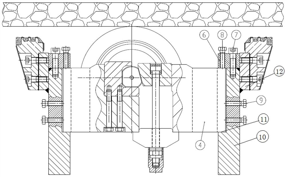
[0023] like image 3 As shown, the cutterhead main beam 1 includes two symmetrically arranged fixed beams 10, and the opposite inner sides of the two fixed beams 10 are provided with shoulders 11 arranged along the radial direction of the shield machine cutterhead, and the hob is assembled The body 4 is fixedly arranged in the two shoulders 11, which not only facilitates the assembly of the hob assembly 4 and the main beam 1 of the cutter head, but also facilitates the adjustment of the position ...
Embodiment 2
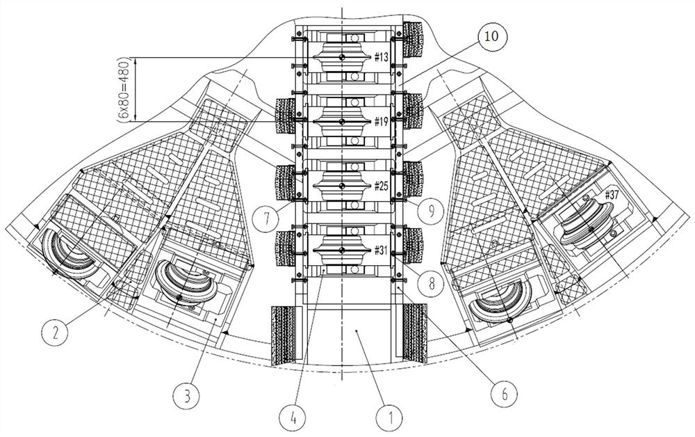
[0029] Embodiment 2, a shield machine cutterhead with variable cutter spacing, such as figure 2As shown, the pressing block 6 is arranged along the radial direction of the main beam of the cutter head 1 and is in the shape of a long strip, so that no matter how the position of the tool box assembly 4 is adjusted, it will be crimped under the pressing block 4 of the tool box. The structure is simplified, and it is convenient to adjust the position of the hob assembly 4 and fix it again.
[0030] The structure of this embodiment is the same as that of Embodiment 1.
Embodiment 3
[0031] Embodiment 3, a shield machine cutterhead with variable cutter spacing, the distance between the pressing bolts 9 adjacent to the side of the cutter box is less than two times the width of the hob assembly 4 along the radial direction of the shield machine cutterhead One-third, it can ensure that no matter how the position of the hob assembly 4 is adjusted, at least two groups of knife box side compression bolts 9 can be crimped on the side of a hob assembly 4.
[0032] The distance between the second pressing bolts 8 adjacent to the front of the cutter box is less than half of the width of the hob assembly 4 along the radial direction of the cutter head of the shield machine. This can ensure that no matter how the position of the hob assembly 4 is adjusted, at least two sets of second compression bolts 8 on the front of the knife box are crimped on the front of one hob assembly 4 .
[0033] The structure of this embodiment is the same as Embodiment 1 or 2.
PUM
 Abstract
Description
Claims
Application Information
 - R&D
- Intellectual Property
- Life Sciences
- Materials
- Tech Scout
- Unparalleled Data Quality
- Higher Quality Content
- 60% Fewer Hallucinations
Browse by: Latest US Patents, China's latest patents, Technical Efficacy Thesaurus, Application Domain, Technology Topic, Popular Technical Reports.
© 2025 PatSnap. All rights reserved.Legal|Privacy policy|Modern Slavery Act Transparency Statement|Sitemap|About US| Contact US: help@patsnap.com


